This study investigates a diesel engine fueled with methanol/diesel blends to examine the effects of varying methanol ratios on combustion and emission characteristics. A three-dimensional computational fluid dynamics (CFD) model of the combustion chamber is developed using CONVERGE 3.0, coupled with a chemical kinetic mechanism generated via the CHEMKIN program, comprising 182 reactions and 52 species. The results indicate that compared to the original engine, methanol/diesel blends reduce peak in-cylinder pressure, maximum temperature, and emissions of NOx, NO, and soot. At a methanol blending ratio of 30%, NOx, NO, and soot emissions are reduced by 41.12%, 66.96%, and 26.54%, respectively.
- Open Access
- Article
Effects of Different Methanol/Diesel Ratios on Engine Performance under Plateau Environment
- Guangyuan Bao *,
- Chao He,
- Jiaqiang Li
Author Information
Received: 15 Jul 2025 | Revised: 22 Aug 2025 | Accepted: 27 Aug 2025 | Published: 03 Sep 2025
Abstract
Keywords
diesel engine | methanol/diesel ratio | combustion characteristics | emission characteristics
1.Introduction
Diesel engines offer advantages such as high thermal efficiency and reliability [1-3], making them an irreplaceable power source for non-road mobile machinery, including agricultural equipment [4]. However, emissions of carbon monoxide (CO), nitrogen oxides (NOx), and particulate matter (PM) from diesel engines pose significant risks to public health and the ecosystem [5]. In response to these challenges, as well as concerns over resource depletion and environmental issues, researchers have increasingly focused on alternative fuels with cleaner combustion characteristics, including ammonia [6], hydrogen [7], methane [8], and alcohol-based fuels [9]. In internal combustion engines, oxygenated fuels can reduce emissions of soot, NOx, CO, carbon dioxide (CO2), and total hydrocarbon (THC), while also improving combustion characteristics [10].
Methanol has attracted widespread attention as an excellent hydrogen carrier. It has the advantages of low carbon content, high octane number, and high oxygen content, and has the potential to achieve a carbon-neutral cycle [11]. In addition, methanol can achieve clean combustion in internal combustion engines and can significantly reduce PM emissions [12]. Compared with liquefied natural gas (LNG), methanol does not need to be stored under low temperature conditions and does not require complex insulation measures, making its fuel storage system simpler in design and construction and more economical [13]. Yao et al. [14] studied diesel/methanol combined combustion (DMCC) and found that DMCC reduced soot and NOx emissions [9]. Berber et al. [15] studied the effect of methanol blending on engines. The results showed that methanol blending can reduce CO2 and CO emissions. Dou et al. [16] showed that as the proportion of methanol increased, the number of PM gradually decreased. Canakci et al. [17] found that as the proportion of methanol blending increases, the maximum explosion pressure and peak heat release rate (HRR) of diesel engines increase significantly. At the same time, increasing the injection pressure can effectively shorten the ignition delay period, thereby improving the reaction speed of the combustion process. Bayraktar et al. [18] studied the effect of different methanol blending ratios on diesel engine performance. The results showed that the engine performance was optimal when the methanol blending ratio was 10%. Liu et al. [19] studied the effect of diesel injection timing on engine emission characteristics in methanol/diesel dual-fuel combustion mode. The results showed that advancing injection timing can increase NOx emissions and reduce soot emissions. Soni et al. [20] employed computational fluid dynamics (CFD) to study the emission characteristics of diesel/methanol blended fuel engines. The results showed that at a methanol blend ratio of 30%, the emissions of NOx, CO, and HC were reduced by 27%, 58%, and 65%, respectively. Jamrozik [21] showed that when the methanol blend ratio increased to 30%, the engine thermal efficiency was significantly improved, but the NOx emissions also increased significantly. Pawar et al. [22] used the Taguchi method to study the effect of cranberry biodiesel blending on the thermal efficiency and emission performance of neem oil biodiesel. The study showed that when 20% of cranberry biodiesel and 20% of neem oil biodiesel were blended in the fuel, the thermal efficiency of the engine increased by 0.98%. Dong et al. [23] investigated the effects of methanol direct injection on the combustion and emission characteristics of a methanol/diesel dual-fuel engine. The results indicate that as the methanol substitution rate increases, both combustion stability and thermal efficiency improve significantly, while CO and HC emissions are notably reduced. Pan et al. [24] studied the impact of different methanol fractions on the performance of a diesel/methanol dual-fuel engine. The results show that when the methanol fraction reaches 60%, the indicated efficiency of the diesel-methanol dual-fuel system increases by 2.4% compared to conventional diesel combustion.
In summary, although a large number of studies have focused on the combustion and emission characteristics of methanol/diesel mixed fuel engines, the relevant research is mainly concentrated in the field of automotive diesel engines. This work takes non-road diesel engines as the research object, combines chemical kinetics mechanism and CFD calculation method, and systematically studies the combustion and emission characteristics of diesel engines under the conditions of different proportions of methanol blending under a plateau environment. The fuel combinations of M0/D100, M5/D95, M10/D90, M15/D85, M20/D80, M25/D75, and M30/D70 were selected as primary fuels. Three-dimensional simulation models were used to investigate the combustion and emission characteristics of methanol in a calibrated engine model under a 2000 m high-altitude environment. The aim is to provide a theoretical basis for low-carbon emission technologies in non-road diesel engines.
2.Model Establishment and Verification
2.1.Model Construction
The engine used in this study is a four-cylinder, four-stroke diesel engine. The main parameters of the engine are provided in Table 1, and the combustion chamber is a deep-pit ω-type. A schematic of the engine test bench is shown in Figure 1. The test was conducted at an altitude of 2000 m, with an atmospheric pressure of 81 kPa in the testing environment. The simulation model parameters were set according to the experimental control parameters. A geometric model of the engine combustion chamber was created using UG NX 2023 software (Version 2023, Siemens Digital Industries Software, Plano, TX, USA) and imported into CONVERGE 3.0 for preprocessing and mesh generation. Subsequently, CFD simulations of the combustion process were conducted. CONVERGE 3.0 utilizes automatically generated dynamic moving meshes, with local mesh refinement applied to the cylinder head, piston crown, and injector nozzle regions to more accurately capture the complex velocity gradients and fuel mixing characteristics in these areas. Since an 8-hole injector design is adopted and the nozzle spacing is evenly distributed, a 1/8 combustion chamber model is adopted. The combustion chamber model is shown in Figure 2. This study primarily investigates the atomization and combustion processes of diesel, and thus, the model was simplified accordingly. In the three-dimensional CFD calculations, the computational domain was defined as the closed region between the intake valve closing (-124 °CA ATDC) and the exhaust valve opening (132 °CA ATDC), to simulate the in-cylinder flow field and chemical reaction characteristics during actual combustion. The engine speed was maintained at 2000 r/min, with intake pressure set at 0.25 MPa and intake temperature at 373 K.
Table 1.
Main technical parameters of the test engine.
| Parameters | Values |
|---|---|
| Engine Type | 4-stroke, 4-valve, direct injection |
| Number of cylinders | 4 |
| Bore × stroke | 95 mm × 105 mm |
| Compression ratio | 16.6:1 |
| Displacement | 2.977 L |
| Number of nozzles | 8 |
| Nozzle hole diameter | 0.135 mm |
| Intake valve closing | -124 °CA ATDC |
| Exhaust valve opening | 132 °CA ATDC |
| Emission standards | Non-road National IV |
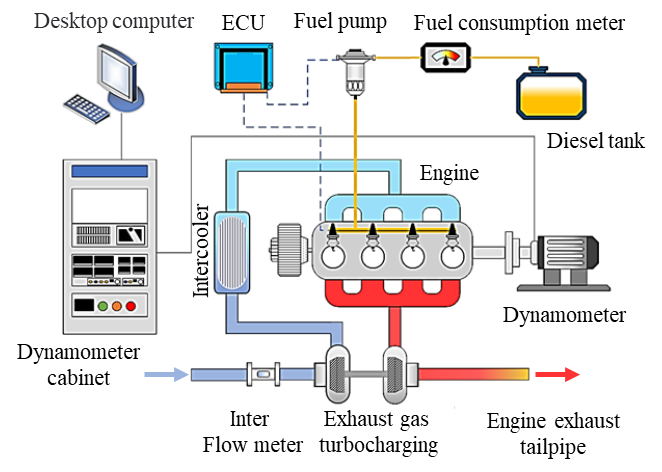
Figure 1.The schematic system of engine.
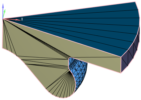
Figure 2.CFD grid model.
Selecting appropriate physical and chemical models is crucial for ensuring the accuracy of combustion process simulations. In terms of turbulence modeling, the Renormalization Group (RNG) k-ε turbulence model [25] was adopted in this study. This model effectively captures the flow characteristics in low Reynolds number regions and demonstrates high accuracy and stability in complex shear flows and vortex scales. In terms of droplet dynamics modeling, in order to accurately describe the collision behavior between droplets and their interaction with the wall during the spray process, the NTC collision model [26] and the O’Rourke model [27] were used for joint modeling. The droplet evaporation process was modeled using the Frossling model [28], which is based on heat and mass transfer theory and can effectively predict the evaporation rate of droplets in different temperature fields. The Kelvin-Helmholtz/Rayleigh-Taylor (KH-RT) model [29] is used to simulate the spray breakup process. This model effectively captures both primary and secondary breakup mechanisms, making it one of the most mature spray modeling methods in current CFD applications. In terms of chemical reactions, the SAGE combustion model [30] is employed, coupling detailed chemical reaction mechanisms to simulate the in-cylinder combustion process of a methanol/n-heptane blended fuel. The adopted kinetic mechanism includes 52 species and 182 reaction steps [31]. Additionally, for pollutant formation, the Extended Zeldovich mechanism is used to predict the generation of NOx, while the Hiroyasu-NSC soot model is applied to describe the formation and oxidation behavior of soot particles.
2.2.Model Validation
The mesh size has a significant impact on the computational efficiency and prediction accuracy of CFD simulations. Larger meshes can increase the computational speed, but it is often difficult to accurately capture key flow characteristics and combustion details. Although too fine a mesh is conducive to improving accuracy, it will significantly increase the computational cost. Therefore, under the premise of ensuring the accuracy of the simulation results, it is particularly important to reasonably select the basic mesh size to balance accuracy and computational efficiency. In order to verify the sensitivity of the simulation results to the mesh size, this paper uses three basic mesh scales, namely coarse mesh (5 mm), medium mesh (4 mm), and fine mesh (3 mm), to carry out mesh independence analysis. Figure 3 shows a comparison of in-cylinder pressure under three different grid conditions. As shown in Figure 3, when the base grid size is 4 mm, further mesh refinement has a negligible impact on in-cylinder combustion. Considering both accuracy and computational efficiency, a 4 mm base grid size is selected for subsequent simulations. Structured hexahedral meshes are automatically generated using CONVERGE software (Version 3.1, Convergent Science, Inc., Madison, WI, USA), incorporating adaptive refinement based on the base grid size and a fixed-area refinement strategy. During the injection duration, mesh refinement is applied to the fuel spray region using a three-level refinement strategy, with the minimum grid size set to 0.5 mm.
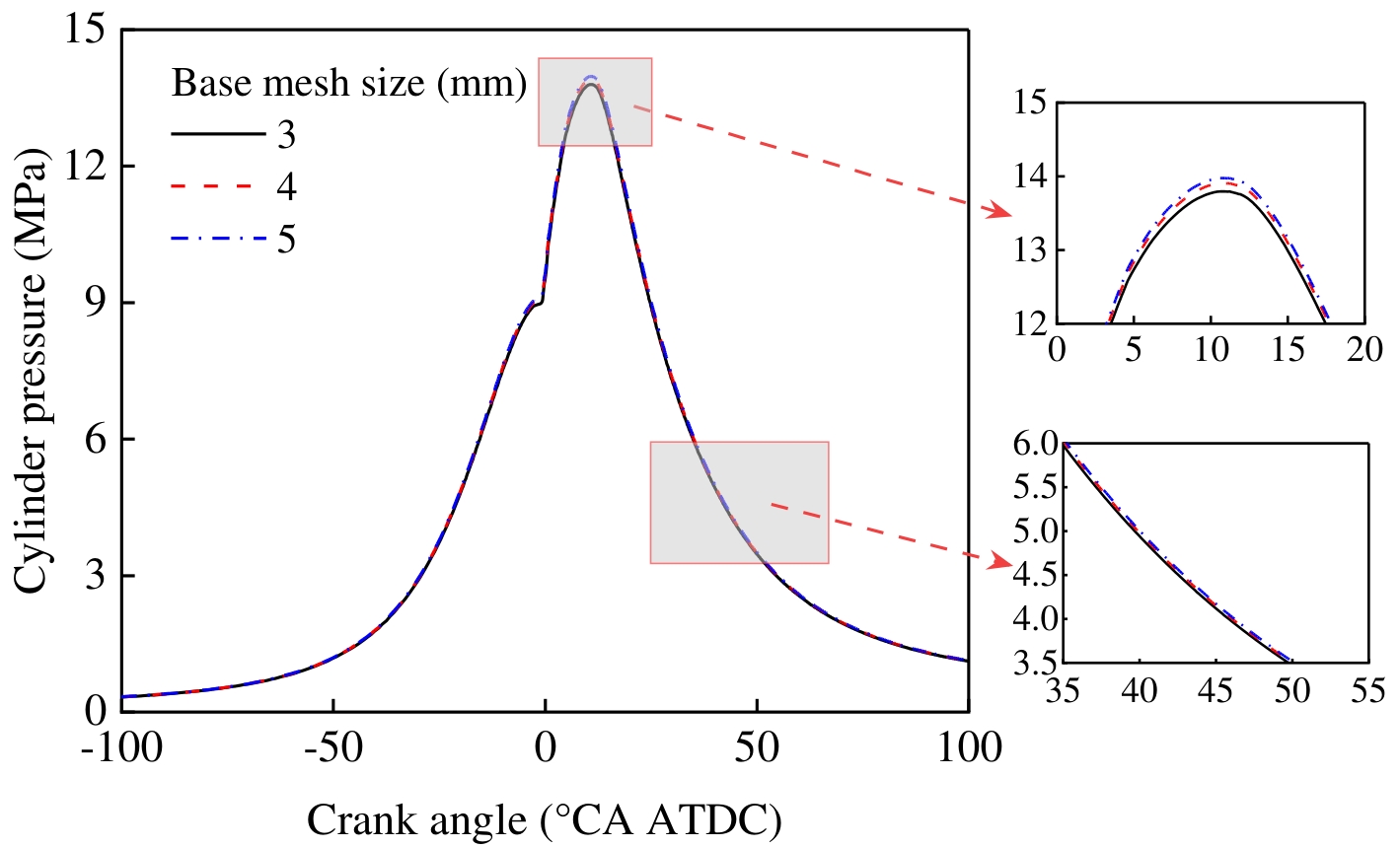
Figure 3.Verification of the sensitivity of the basic grid size.
Figure 4 shows the effect of different methanol/diesel ratios on the in-cylinder pressure and HRR. As shown in Figure 4, with the increase of the methanol mixing ratio, the in-cylinder peak pressure and HRR both show a downward trend. Li et al. [32] showed that too high a methanol mixing ratio will lead to deterioration of combustion and cause knock. Therefore, in order to ensure the stability and safety of combustion, this paper sets the upper limit of the methanol mixing ratio to 30%. With the increase of the methanol mixing ratio, the in-cylinder peak pressure gradually decreases, and the combustion start time is delayed.
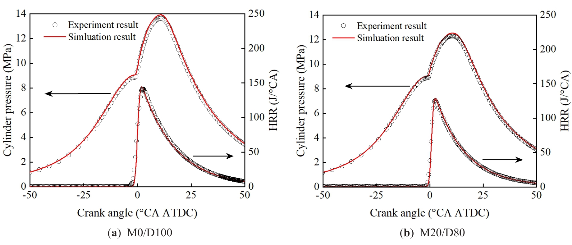
Figure 4.Comparison of test and simulation values of cylinder pressure and HRR.
3.Results and Discussions
3.1.Effect of Methanol/Diesel Ratio on Engine Cylinder Pressure
Figure 5 shows the effect of different methanol/diesel blending ratios on in-cylinder pressure. As shown in Figure 5, the maximum in-cylinder pressure gradually decreases with the increasing methanol blend ratio. At M30/D70, the maximum in-cylinder pressure is 11.79 MPa, which represents a 15.22% decrease compared to the M0/D100. This can be attributed to the fact that the heating value of methanol is only 46.26% that of diesel, which is significantly lower. As the methanol blend ratio increases, the overall heating value and energy content of the fuel mixture decrease, leading to less energy being released during combustion. This reduction in energy results in lower in-cylinder pressure.
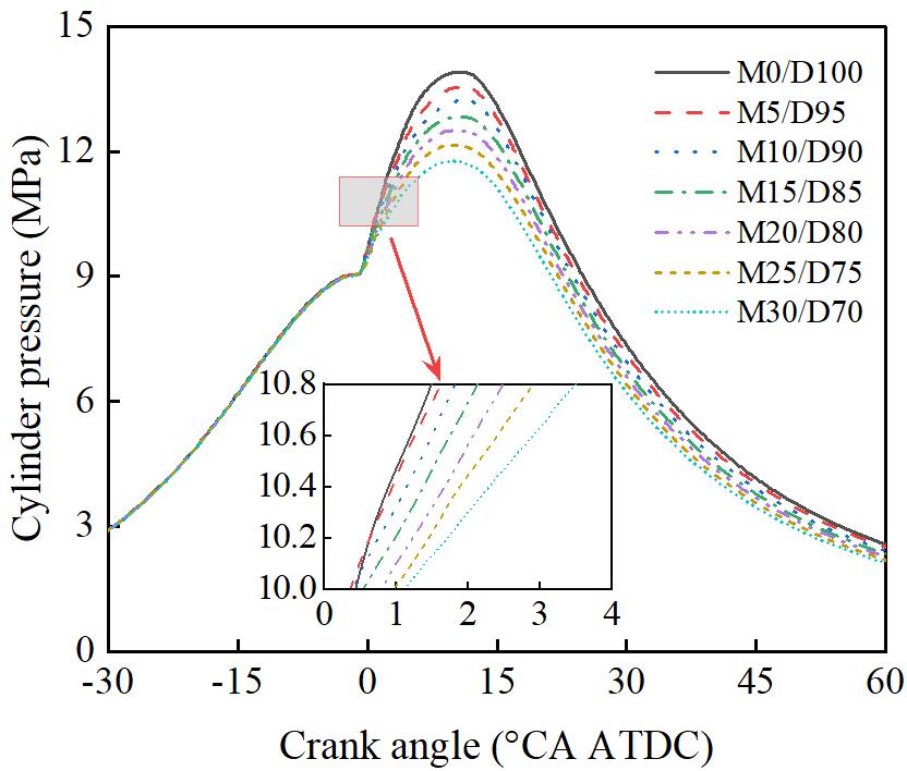
Figure 5.Effect of methanol blending ratio on cylinder pressure.
3.2.Effect of Methanol/Diesel Ratio on Engine Cylinder Temperature
Figure 6 shows the effect of different methanol/diesel blending ratios on in-cylinder temperature. As shown in Figure 6, the peak in-cylinder temperature gradually decreases with an increasing methanol blend ratio. At M30/D70, the peak in-cylinder temperature is reduced by 11.71% compared to the M0/D100. This can be attributed to the higher vaporization latent heat of methanol compared to diesel. Increasing the methanol ratio requires more heat for the vaporization of the methanol/diesel fuel mixture. When methanol is blended with diesel, it not only lowers the compression temperature but also reduces the combustion temperature. Furthermore, the lower heating value of methanol, which is less than half that of diesel, results in a reduced amount of heat released during the combustion process, further decreasing the in-cylinder temperature.
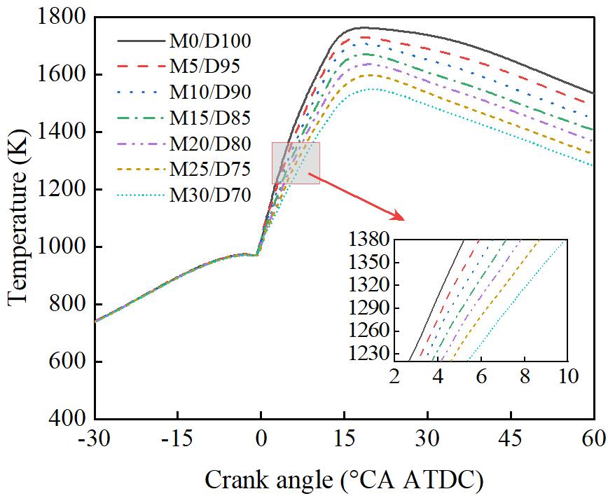
Figure 6.Effect of methanol blending ratio on cylinder temperature.
3.3.Effect of Methanol/Diesel Ratio on Engine Emission Performance
Figure 7 shows the effect of different methanol/diesel mixing ratios on NOx emissions. As shown in Figure 7, as the methanol mixing ratio increases, the NOx emission concentration in the engine exhaust gradually decreases. At M30/D70, the NOx emission concentration reaches the lowest value, which is 41.12% lower than that of M0/D100. This is because methanol has a higher latent heat of vaporization. After mixing with methanol, the engine intake temperature and combustion temperature are both reduced, thereby reducing the generation of NOx.
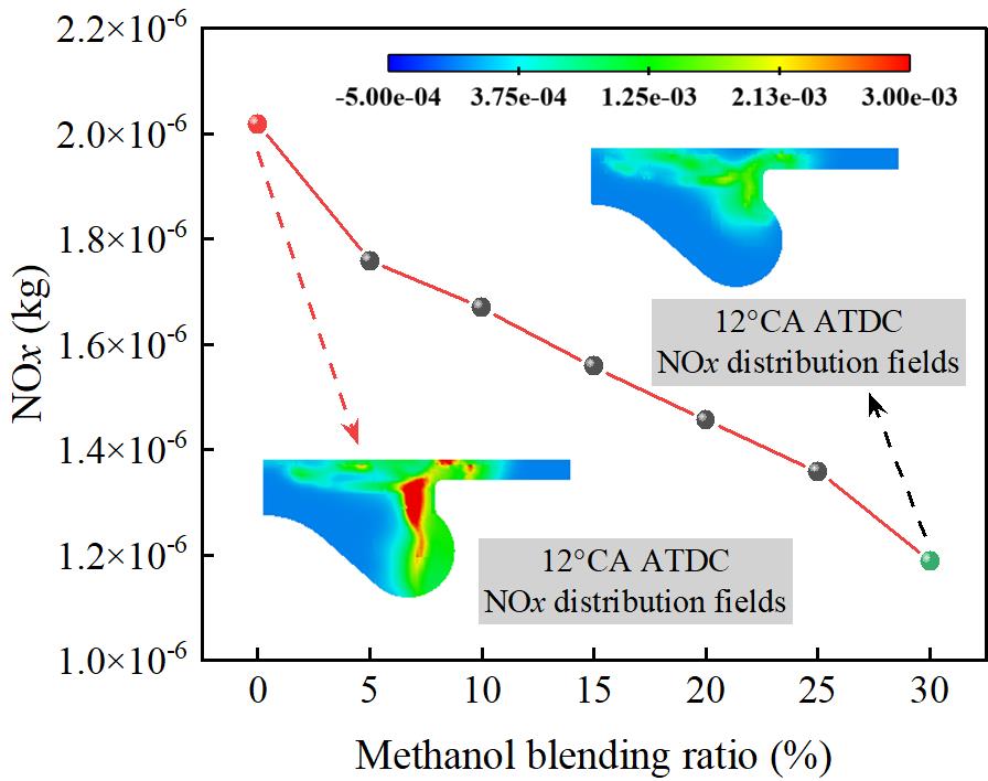
Figure 7.Effect of methanol blending ratio on NOx.
Figure 8 shows the effect of different methanol/diesel blend ratios on NO emissions. As shown in Figure 8, NO emissions decrease significantly with an increase in the methanol blend ratio. At M30/D70, NO emissions reach their lowest point, showing a 66.96% reduction compared to the M0/D100. The formation of NO is highly dependent on the localized high-temperature environment during combustion, particularly the peak temperature and the duration of high temperatures. Methanol, with its high latent heat of vaporization, absorbs a considerable amount of heat during the initial vaporization stage, which results in a reduction in peak in-cylinder temperature and a shorter duration of high temperatures. This process effectively suppresses the formation of thermal NO. Furthermore, since methanol does not contain nitrogen, the overall nitrogen-containing components participating in the combustion reaction decrease, further reducing the potential for NO formation.
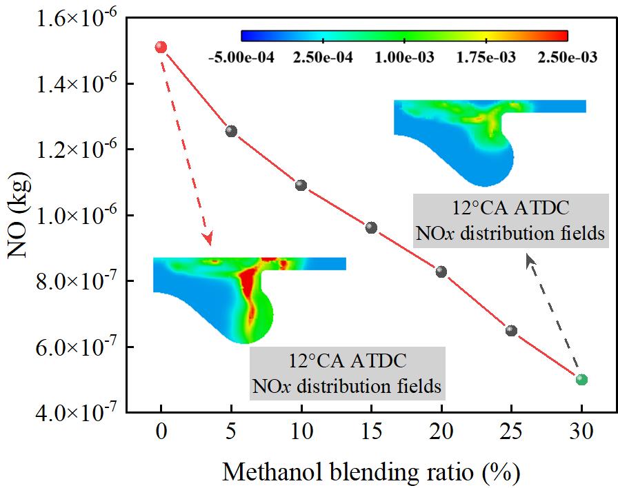
Figure 8.Effect of methanol blending ratio on NO.
Figure 9 shows the effect of different methanol/diesel blend ratios on soot emissions. As shown in Figure 9, Soot emissions significantly decrease with an increase in the methanol blend ratio. At M30/D70, soot emissions reach their lowest level, with a 26.54% reduction compared to the M0/D100. This is due to methanol’s high latent heat of vaporization, which absorbs a significant amount of heat during the spray evaporation process, thereby lowering the local in-cylinder temperature. This reduction suppresses the formation of localized rich fuel zones, weakens the pyrolysis reactions under high-temperature, oxygen-deficient conditions, and consequently reduces soot formation. Additionally, since methanol molecules lack C–C bonds, the formation of polycyclic aromatic hydrocarbons and other soot precursors is limited during combustion, effectively inhibiting the soot formation pathway. Therefore, with an increase in the methanol blend ratio, the combustion process becomes cleaner, leading to a significant reduction in soot emissions.
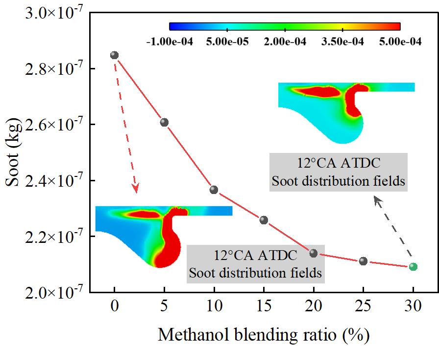
Figure 9.Effect of methanol blending ratio on soot.
Figure 10 shows the effect of different methanol/diesel blending ratios on CO emissions. As shown in Figure 10, as the methanol blending ratio increases, CO emissions show a clear upward trend. At M30/D70, the CO emission concentration reaches a peak, which is 44.23 times higher than that of M0/D100. Since methanol is a low-carbon fuel, increasing the methanol blending ratio will lead to an increase in the carbon content of the mixed fuel. Therefore, as the methanol blending ratio increases, the CO emission concentration in the engine exhaust gas gradually increases. When the methanol blending ratio reaches 30%, the CO emission concentration reaches the highest value. The main reason for this phenomenon is that the oxidation reaction of CO requires the participation of active OH radicals, and the addition of methanol will convert some active OH radicals into inactive H2O2, which will lead to a decrease in the CO oxidation rate, thereby increasing CO emissions.
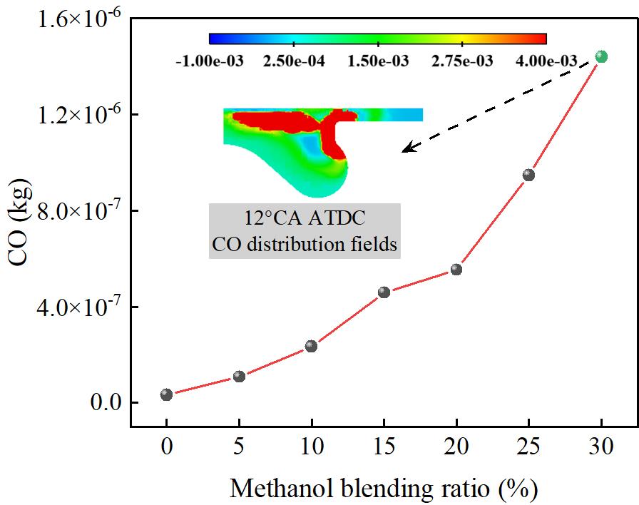
Figure 10.Effect of methanol blending ratio on CO.
4.Conclusions
(1) With the increase of the methanol blending ratio, the in-cylinder pressure and temperature of the engine showed a consistent change trend, both decreasing to varying degrees. The maximum in-cylinder explosion pressure and the maximum combustion temperature decreased by 15.22% and 11.71% respectively, compared with the original engine.
(2) As the methanol blend ratio increases, NOx, NO, and soot emissions all show a clear downward trend, with the most significant reduction at M30/D70. Compared with M0/D100, NOx, NO, and soot emissions decreased by 41.2%, 66.96%, and 26.54%, respectively. This result demonstrates that methanol, as an alternative fuel, has significant potential for emission reductions.
(3) With the increase of the methanol blending ratio, CO emissions increased significantly, and the increase was the largest when the methanol blending ratio was 30%. Compared with the original engine, CO emissions increased by 44.23 times.
Author Contributions: G.B.: software, methodology, validation, investigation, formal analysis, visualization, writing—original draft, writing—review & editing; C.H.: software, methodology, validation; J.L.: project administration, investigation, formal analysis. All authors have read and agreed to the published version of the manuscript.
Funding: This work was supported by the National Natural Science Foundation of China (Grant No. 51968065) and the Yunnan Provincial Department of Education Science Research Fund Project (Grant No. 2024Y605). This work was supported by the Yunnan Provincial Science and Technology Department Agricultural Joint Project (Grant No. 202301BD070001-077).
Institutional Review Board Statement: Not applicable.
Informed Consent Statement: Not applicable.
Data Availability Statement: The data that support the findings of this study are available from the corresponding author upon reasonable request.
Conflicts of Interest: The authors declare that they have no known competing financial interests or personal relationships that could have appeared to influence the work reported in this paper.
Nomenclature
|
CO |
Carbon monoxide |
LNG |
Liquefied natural gas |
|
NOx |
Nitrogen oxides |
DMCC |
Diesel/methanol compound combustion |
|
PM |
Particulate matter |
HRR |
Heat release rate |
|
CO2 |
Carbon dioxide |
CFD |
Computational fluid dynamics |
References
- 1.
Bao, G; He, C; Zi, T; Li, J; Liu, X; Analysis of gas flow and PM movement characteristics inside diesel particulate filter channel. Process Saf. Environ. Prot. 2024, 186, 1134–1148.
- 2.
Yin, Y; Mi, J; Zhao, Y; Liu, Z; Research on Electrical Boost Technology for Medium-Duty Diesel Engines. Int. J. Automot. Manuf. Mater. 2025, 4, 4.
- 3.
Wang, D; Bao, G; He, C; Li, J; Chen, Y; Zhao, L; Yu, H; Investigation of the Impact of Combustion Chamber Geometry on Engine Combustion and Emission Performance Under Various Fuel Injection Timings with Biodiesel Blending. Energy Sci. Eng. 2025, 13, 268–289.
- 4.
Liu, F; Shafique, M; Luo, X; Literature review on life cycle assessment of transportation alternative fuels. Environ. Technol. Innov. 2023, 32, 103343.
- 5.
Wang, B; Wang, H; Yang, C; Hu, D; Duan, B; Wang, Y; Effect of different ammonia/methanol ratios on engine combustion and emission performance. Appl. Therm. Eng. 2024, 236, 121519.
- 6.
Zhu, D; Shu, B; Recent Progress on Combustion Characteristics of Ammonia-Based Fuel Blends and Their Potential in Internal Combustion Engines. Int. J. Automot. Manuf. Mater. 2023, 2, 1.
- 7.
Ren, L; Zhou, S; Ou, X; Life-cycle energy consumption and greenhouse-gas emissions of hydrogen supply chains for fuel-cell vehicles in China. Energy 2020, 209, 118482.
- 8.
Zhang, Q; Tang, A; Cai, T; Huang, Q; Analysis of entropy generation and exergy efficiency of the methane/dimethyl ether/air premixed combustion in a micro-channel. Int. J. Heat Mass Transf. 2024, 218, 124801.
- 9.
Yao, A; Yao, C; Study of Diesel/Methanol Dual Fuel Combustion in CI Engines and Its Practice in China. Int. J. Automot. Manuf. Mater. 2023, 2, 2.
- 10.
Huang, Z; Huang, J; Luo, J; Hu, D; Yin, Z; Performance enhancement and emission reduction of a diesel engine fueled with different biodiesel-diesel blending fuel based on the multi-parameter optimization theory. Fuel 2022, 314, 122753.
- 11.
Lu, Y; Wei, M; Wang, X; Wu, P; Zhao, W; Ji, Q; Wang, X; Liu, J; Numerical study of nozzle hole number and pre-injection timing effect on combustion and emissions of methanol/diesel dual-fuel engine. Int. Commun. Heat Mass Transf. 2025, 161, 108512.
- 12.
Wang, Z; Li, M; Yu, W; Hu, Z; Li, L; The Effects of Ignition Delay and Fuel Injection Duration on Sparked-Spray Combustion Using Gasoline and Methanol in the Atmospheric Environment. Int. J. Automot. Manuf. Mater. 2025. https://doi.org/10.53941/ijamm.2025.100014.
- 13.
Bayraktar, M; Yuksel, O; Pamik, M; An evaluation of methanol engine utilization regarding economic and upcoming regulatory requirements for a container ship. Sustain. Prod. Consum. 2023, 39, 345–356.
- 14.
Yao, C; Cheung, C.S; Cheng, C; Wang, Y; Reduction of smoke and NOx from diesel engines using a diesel/methanol compound combustion system. Energy Fuels 2007, 21, 686–691.
- 15.
Berber, A. The effect of diesel-methanol blends with volumetric proportions on the performance and emissions of a diesel engine. Mechanics 2019, 25, 363–369.
- 16.
Dou, Z; Yao, C; Wei, H; Wang, B; Liu, M; Chen, C; Gao, J; Shi, J; Experimental study of the effect of engine parameters on ultrafine particle in diesel/methanol dual fuel engine. Fuel 2017, 192, 45–52.
- 17.
Canakci, M; Sayin, C; Ozsezen, A.N; Turkcan, A; Effect of injection pressure on the combustion, performance, and emission characteristics of a diesel engine fueled with methanol-blended diesel fuel. Energy Fuels 2009, 23, 2908–2920.
- 18.
Bayraktar, H. An experimental study on the performance parameters of an experimental CI engine fueled with diesel–methanol–dodecanol blends. Fuel 2008, 87, 158–164.
- 19.
Liu, J; Yao, A; Yao, C; Effects of diesel injection pressure on the performance and emissions of a HD common-rail diesel engine fueled with diesel/methanol dual fuel. Fuel 2015, 140, 192–200.
- 20.
Soni, D.K; Gupta, R; Optimization of methanol powered diesel engine: A CFD approach. Appl. Therm. Eng. 2016, 106, 390–398.
- 21.
Jamrozik, A. The effect of the alcohol content in the fuel mixture on the performance and emissions of a direct injection diesel engine fueled with diesel-methanol and diesel-ethanol blends. Energy Convers. Manag. 2017, 148, 461–476.
- 22.
Pawar, S; Hole, J; Bankar, M; Channapattana, S; Srinidhi, C; Use of Taguchi method for optimizing engine parameters of variable compression ratio diesel engine using Cocklebur seed oil biodiesel blended with Karanja oil biodiesel. Mater. Today Proc. 2023. https://doi.org/10.1016/j.matpr.2023.08.129.
- 23.
Dong, Y; Kaario, O; Hassan, G; Ranta, O; Larmi, M; Johansson, B; . High-pressure direct injection of methanol and pilot diesel: A non-premixed dual-fuel engine concept. Fuel 2020, 277, 117932.
- 24.
Pan, X; Guan, W; Gu, J; Wang, X; Zhao, H; Optimization of the low-load performance and emission characteristics for a heavy-duty diesel engine fueled with diesel/methanol by RSM-NSWOA. Renew. Energy 2025, 245, 122819.
- 25.
Han, Z; Reitz, R.D; Turbulence modeling of internal combustion engines using RNG κ-ε models. Combust. Sci. Technol. 1995, 106, 267–295.
- 26.
O’Rourke, P.J; Amsden, A.A; The TAB Method for Numerical Calculation of Spray Droplet Breakup; SAE Technical Paper; SAE: Warrendale, PA, USA, 1987.
- 27.
O’Rourke, P.J; Amsden, A.A; A spray/wall interaction submodel for the KIVA-3 wall film model. SAE Trans. 2000, 109, 281–298.
- 28.
Nazemi, M; Shahbakhti, M; Modeling and analysis of fuel injection parameters for combustion and performance of an RCCI engine. Appl. Energy 2016, 165, 135–150.
- 29.
Ren, Y; Li, X; Assessment and validation of liquid breakup models for high-pressure dense diesel sprays. Front. Energy 2016, 10, 164–175.
- 30.
Senecal, P.K; Pomraning, E; Richards, K.J; Briggs, T.E; Choi, C.Y; McDavid, R.M; Patterson, M.A; Multi-dimensional modeling of direct-injection diesel spray liquid length and flame lift-off length using CFD and parallel detailed chemistry. SAE Trans. 2003, 112, 1331–1351.
- 31.
Liu, S; Sun, T; Zhou, L; Jia, M; Zhao, W; Wei, H; A new skeletal kinetic model for methanol/n-heptane dual fuels under engine-like conditions. Energy 2023, 263, 125648.
- 32.
Li, Z; Wang, Y; Yin, Z; Gao, Z; Wang, Y; Zhen, X; To achieve high methanol substitution ratio and clean combustion on a diesel/methanol dual fuel engine: A comparison of diesel methanol compound combustion (DMCC) and direct dual fuel stratification (DDFS) strategies. Fuel 2021, 304, 121466.
How to Cite
Bao, G.; He, C.; Li, J. Effects of Different Methanol/Diesel Ratios on Engine Performance under Plateau Environment. International Journal of Automotive Manufacturing and Materials 2025, 4 (4), 2. https://doi.org/10.53941/ijamm.2025.100020.
RIS
BibTex
Copyright & License

Copyright (c) 2025 by the authors.
This work is licensed under a Creative Commons Attribution 4.0 International License.
Contents
Figures
References
 Suite 4002 Level 4, 447 Collins Street, Melbourne, Victoria 3000, Australia
 General Inquiries: info@sciltp.com