Based on the Arrhenius equation and actual measuring data of the aftertreatment, the article gives the aftertreatment aging life as a function of aftertreatment temperature. The regeneration interval and temperature depend on the latitude, ambient temperature, and vehicle driving conditions. Taking all these factors into account, the article derives the final integrated formula of the aftertreatment aging mileage. The model and method used in this article are applicable to aftertreatment systems used on both gasoline and diesel engines. They can be used for the temperature calibration of the engine aftertreatment systems.
- Open Access
- Article
The Calculation Method and Mathematical Model for Predicting Engine Aftertreatment Aging Mileage Based on Actual Driving Conditions
- Jie Liu *,
- Xiaowen Qiang,
- Jifeng Deng,
- Xiao Zhang,
- Wei Zhai,
- Yunwei Yao,
- Bo Zhou,
- Shihua Li,
- Qi Zhang
Author Information
Received: 29 Aug 2025 | Revised: 12 Sep 2025 | Accepted: 25 Sep 2025 | Published: 10 Oct 2025
Abstract
Keywords
diesel aftertreatment system | aftertreatment aging | regeneration temperature | aging mileage | Arrhenius equation
1.Introduction
In accordance with “the Environmental Protection Law of the People’s Republic of China” and “the Air Pollution Prevention and Control Law of the People’s Republic of China”, and to prevent and control vehicle exhaust pollution, improving air quality, and winning the battle to protect blue sky, the Ministry of Ecology and Environment officially released the “GB18352.6-2016 Limits and Measurement Methods for Emissions from Light-Duty Vehicles (China Ⅵ)” in December 2016. Starting from 1 July 2020, all light-duty vehicles produced, sold, and registered must comply with the China VI emission standards.
To meet the requirements of the China VI emission regulations, the standard aftertreatment technology solution for domestically produced automotive diesel engines predominantly adopts a configuration of EGR + DOC + DPF + SCR + ASC.
GB17691-2018 specifies clear requirements for the durability of emission control devices. Various types of vehicles must comply with the stipulated effective service life periods for their emission control devices. Manufacturers must ensure the materials, manufacturing processes, and product quality of emission-related components to guarantee their normal functionality throughout the effective service life period. For instance, M1, N1, and M2 vehicles have an effective service life of 200,000 km or 5 years of actual use, whichever comes first.
Currently, the most direct and authoritative method for measuring the aging mileage of aftertreatment systems (i.e., the mileage over which emissions compliance is maintained) is the durability testing method. However, this method is extremely time-consuming and costly. Based on bench test data, this paper establishes a relatively accurate computational model and method for predicting the aging mileage of aftertreatment systems. This model considers actual vehicle driving cycles and the climatic conditions of the vehicle’s usage region, offering significant guidance value for engine and vehicle calibration.
2.Diesel Engine Aftertreatment Solutions and Their Functions
The schematic diagram of the standard aftertreatment system for China VI diesel engines is shown in Figure 1 [1,2].
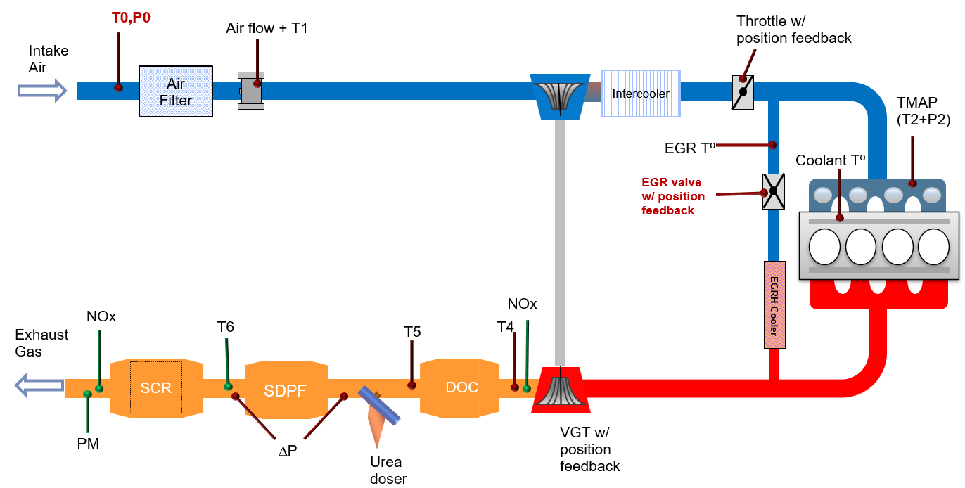
Figure 1.The schematic diagram of the aftertreatment.
The functions and working principles of each major component of the aftertreatment system are as follows:
The EGR (Exhaust Gas Recirculation) system is primarily used to reduce NOx (Nitrogen Oxides) emissions. Its core principle involves recirculating a portion of the exhaust gas back into the engine cylinders. This reduces the peak combustion temperature and lowers the oxygen concentration within the cylinders, thereby inhibiting the formation of NOx [3].
The DOC (Diesel Oxidation Catalyst) is the core component of the diesel engine aftertreatment system. Its main functions are to oxidize CO (Carbon Monoxide), HC (Hydrocarbons), and a portion of the particulate matter (specifically the SOF). Simultaneously, it can oxidize nitric oxide (NO) in the exhaust gas into highly reactive nitrogen dioxide (NO2), which assists the operation of subsequent systems such as the DPF (Diesel Particulate Filter) and SCR (Selective Catalytic Reduction).
DPF (Diesel Particulate Filter) is the core component of the diesel engine aftertreatment system. It can capture and remove particulate matter (PM) from exhaust gas, including soot and the soluble organic fraction (SOF). The DPF is the critical technology for meeting China VI and more stringent emission standards.
SCR (Selective Catalytic Reduction) is the core technology within the diesel aftertreatment system for reducing NOx (Nitrogen Oxides) emissions. Its working principle involves using urea-water solution (i.e., AdBlue) as reducing agent. Under the action of the chemical reaction, SCR can convert NOx into harmless nitrogen (N2) and water (H2O).
ASC (Ammonia Slip Catalyst) is a crucial component located downstream of SCR. Its primary function is to convert unconsumed ammonia (NH3) that escapes from the SCR into harmless nitrogen (N2) and water (H2O), thereby preventing environmental pollution caused by ammonia slip [4,5].
3.Aftertreatment Regeneration and Aging
The DPF studied in this paper is SDPF (SCR-coated DPF), and its regeneration process utilizes a periodic active regeneration mode. The working principle and regeneration mechanism are as follows:
During normal operation, the engine DPF effectively captures soot and adsorbs SOF (generated from unburned fuel and engine oil). The overall filtration efficiency is above 90%. This specific DPF has a substrate volume of 3.3 L. The maximum theoretical soot loading capacity per unit volume of the substrate is 7 g/L, resulting in a maximum theoretical total soot loading capacity of 23.1 g for the DPF. When the accumulated soot mass reaches a predetermined threshold, the ECU triggers DPF regeneration. During the regeneration process, the accumulated PM was burned off and converted into carbon dioxide (CO2). This can restore the DPF’s filtration efficiency and maintain proper engine performance [6].
Within the vehicle’s ECU software, DPF regeneration is triggered based on the following three independent strategies:
Mode 1. DPF Raw Emission Model: Calculates soot accumulation based on engine operating conditions.
Mode 2. DPF Pressure Difference Model: Monitors the pressure drop across the DPF, which increases with soot accumulation.
Mode 3. DPF Mileage Model: Triggers regeneration after a predetermined driving distance has been traveled [7].
To ensure operational safety and margin, the soot load threshold set in each of these three models is kept below the absolute maximum theoretical capacity of the DPF. For the diesel engine in this study, the trigger threshold for all three models is set at 20 g. During actual vehicle operation, the regeneration process is initiated by whichever model first reaches its predefined 20 g soot load threshold. Taking the pickup truck model studied in this paper as an example, the measured DPF soot accumulation results under hot weather, high-altitude, and cold weather conditions are shown in Table 1 below. The mileage values listed in the table are in kilometers (km), and all vehicles were operating under full load conditions.
Table 1.
Soot accumulation mileage under typical environmental conditions.
| Vehicle Driving Conditions | Soot Accumulation Mileage | |||
|---|---|---|---|---|
| Mode 1 | Mode 2 | Mode 3 | Actual | |
| Urban of Turpan | 624 | 857 | 434 | 430 |
| Suburban of Turpan | 905 | 1215 | 499 | 500 |
| Highway of Turpan | 1535 | 1188 | 571 | 570 |
| Urban of Golmud | 1088 | 1126 | 499 | 500 |
| Suburban of Golmud | 1136 | 1256 | 536 | 530 |
| Highway of Golmud | 849 | 956 | 571 | 570 |
| Urban of Dunhuang | 754 | 631 | 421 | 420 |
| Suburban of Dunhuang | 784 | 659 | 443 | 440 |
| Highway of Dunhuang | 873 | 626 | 463 | 460 |
| Urban of Hailar | 678 | 1130 | 532 | 530 |
| Suburban of Hailar | 987 | 1008 | 537 | 530 |
| Highway of Hailar | 647 | 665 | 574 | 570 |
As the regeneration mode is triggered, the ECU employs a coordinated strategy of post-injection and intake throttling (closing the EGR valve while partially closing the throttle valve) to oxidize unburned diesel fuel within the DOC. The heat released during this process will raise the temperature of the aftertreatment system. The elevated temperature enables the accumulated soot in the DPF (Diesel Particulate Filter) to undergo direct oxidation with oxygen, converting it into carbon dioxide.
To ensure high regeneration efficiency (typically exceeding 90%), the temperature of the DPF substrate must be elevated to and maintained within the range of 550–650 °C.
Due to the initial combustion of unburned diesel fuel occurring within the DOC, DOC’s temperature becomes exceptionally high during the regeneration process. Under extreme transient conditions, the peak temperature can approach or even exceed 800 °C [8].
For DOCs utilizing a cordierite substrate, prolonged exposure to temperatures exceeding 750 °C causes the precious metals (Pt/Pd) within the washcoat to undergo particle sintering (where particles grow from approx. 3 nm to 20 nm). This phenomenon accelerates the aging of the aftertreatment system, leading to a significant degradation in the DOC’s catalytic conversion efficiency [9].
The relationship between the aging time of the aftertreatment system and its operating temperature is typically modeled using the Arrhenius equation. The formula for aging time based on thermal exposure is as follows [10,11]:
In the above equation, A is the lifetime pre-exponential factor, which is specific to the particular aftertreatment system and remains constant for the given system; L represents the equivalent aging time of the aftertreatment at temperature T; Eₐ denotes the activation energy of the aging reaction (unit: J/mol); R is the universal gas constant i.e., 8.314 J/(mol·K); and T represents the absolute operating temperature of the aftertreatment system, in units of Kelvin (K).
Taking the DOC aftertreatment system studied in this paper as an example, the data illustrating the variation of its equivalent aging time with temperature is presented in Table 2 below.
Table 2.
Equivalent aging time with temperature.
| Temp of DOC (℃) | Actual Aging Time (h) | Model Aging Time (h) | Relative Error |
|---|---|---|---|
| 650 | 300 | 299.9 | -0.023% |
| 660 | 245.1 | 244.8 | -0.112% |
| 670 | 200.7 | 200.7 | 0.003% |
| 680 | 165 | 165.2 | 0.136% |
| 690 | 136.5 | 136.6 | 0.049% |
| 700 | 113.4 | 113.3 | -0.069% |
| 710 | 94.5 | 94.4 | -0.115% |
| 720 | 78.6 | 78.9 | 0.398% |
| 730 | 66.3 | 66.2 | -0.138% |
| 740 | 55.8 | 55.7 | -0.103% |
| 750 | 47.1 | 47.1 | -0.024% |
The aging time formula for this specific DOC, fitted according to the Arrhenius equation, is as follows:
The calculated results obtained by fitting the measured DOC data according to the Arrhenius equation show excellent agreement with the actual values. Within the temperature range of 650–750 °C, the relative error is consistently within 0.5%. The curve depicting the variation of aging time with temperature is shown in Figure 2 below:
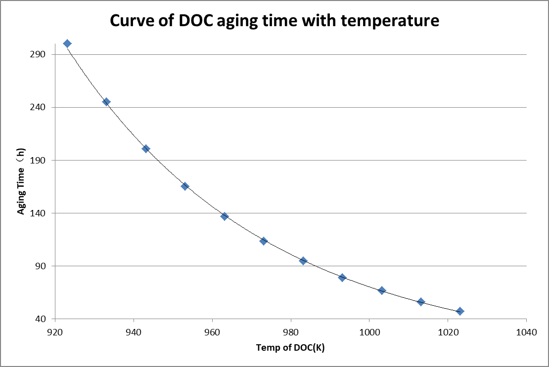
Figure 2.Curve of DOC aging time with temperature.
4.Aftertreatment Regeneration Temperature Management and Calibration
From Table 2, it can be seen that the aftertreatment aging time is reduced to only 15.7% of its initial value when the aftertreatment temperature increases from 650 °C to 750 °C. Therefore, precise control of regeneration temperature is critical during the aftertreatment calibration process.
If the temperature is too low (<550 °C), incomplete combustion of soot will occur, leading to regeneration failure and DPF blockage. This may trigger relevant DTCs, activate the driver induction system, result in engine derating that affects vehicle usability, and could even cause damage to the aftertreatment system.
Conversely, excessively high temperatures will accelerate aftertreatment aging. If the temperature exceeds certain limits (>750 °C), there is a risk of thermal stress-induced cracking of the substrate due to localized overheating.
The DPF regeneration temperature control strategy primarily involves the calibration of post-injection fuel quantity, injection timing, electronic throttle valve position, and EGR valve opening. Through these technical measures, the DPF inlet temperature is maintained within the range of 550–650 °C (depending on the substrate and catalyst type) [12].
The typical regeneration temperature calibration process involves: installing multiple thermocouple temperature sensors (common sensor locations are shown in Figure 3) in the aftertreatment system; calibrating and testing the regeneration temperature on the engine test bench, during this process, the discrepancies between the measured values from the sensors and the estimated values from the temperature model are checked and corrected if necessary. After the bench calibration is completed, real-road tests are carried out to validate the model’s robustness under various actual environmental conditions. Additionally, temperature inspections under extreme operating conditions are performed to ensure that the maximum exhaust temperature does not exceed the predefined limit across all driving modes and scenarios [13,14].
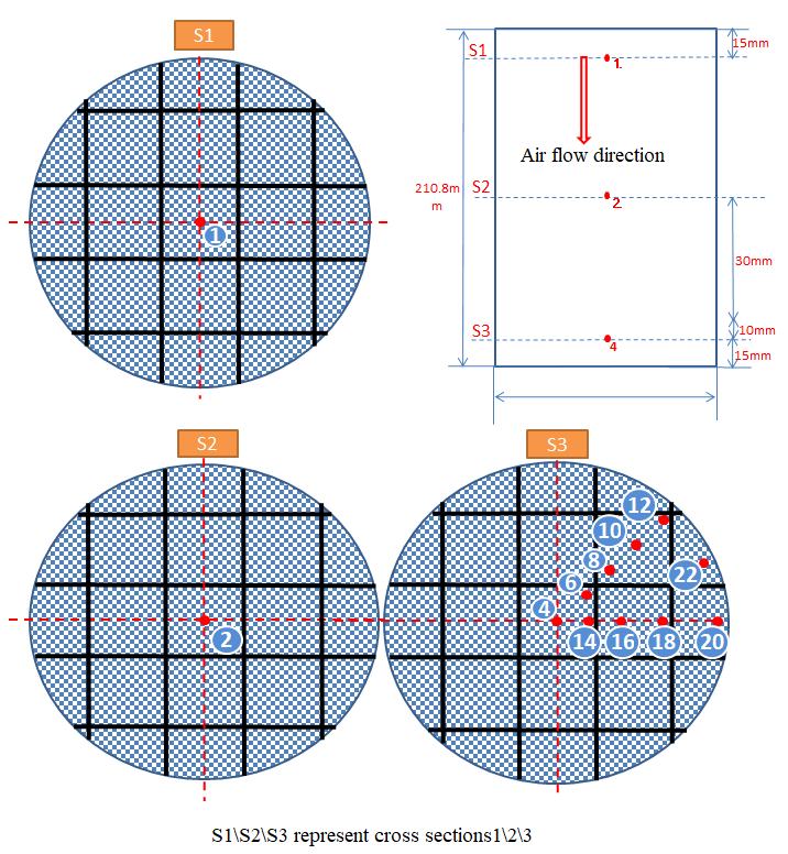
Figure 3.Thermocouple layout in aftertreatment.
The pickup truck model investigated in this study underwent calibration tests under various conditions, including plain areas at normal temperature, high-temperature conditions in Turpan, plateau environments in Golmud and Dunhuang, as well as extreme cold conditions in Hailar. The exhaust temperatures of the aftertreatment system were monitored under each typical road condition, and the measured temperature data are presented in Table 3.
Table 3.
The measured temperature data under each typical road condition.
| Location | Turpan | Dunhuang | Hailar | ||||||
|---|---|---|---|---|---|---|---|---|---|
| Driving Condition | Urban | Suburban | Highway | Urban | Suburban | Highway | Urban | Suburban | Highway |
| Temp DOC Inlet (℃) | 372 | 440 | 467 | 403 | 397 | 480 | 351 | 439 | 488 |
| Temp DOC IN BED (℃) | 680 | 681 | 667 | 673 | 685 | 648 | 658 | 688 | 677 |
| Temp DOC OUT BED (℃) | 612 | 621 | 609 | 687 | 699 | 661 | 673 | 701 | 687 |
| Temp DPF Inlet (℃) | 597 | 616 | 607 | 613 | 616 | 615 | 594 | 617 | 621 |
| Temp DPF Core BED (℃) | 597 | 616 | 607 | 615 | 618 | 617 | 589 | 614 | 618 |
| Regeneration Duration (s) | 1312 | 1450 | 1556 | 1317 | 1327 | 1430 | 1647 | 1549 | 1610 |
5.Aftertreatment Aging Mileage Calculation Model
During vehicle road testing, the VISU software can be used to collect real-time temperature values at each measurement point of the aftertreatment system. After obtaining the temperature data, the DOC aftertreatment regeneration process is divided into intervals of every 10 °C. The duration of the entire regeneration process within each temperature interval is then accumulated. By combining with the fitted Equation (2) mentioned earlier, the aging proportion of the aftertreatment system during a complete regeneration process can be calculated using the following formula:
In the above equation, represents the duration in the i-th temperature interval during one complete regeneration process, in units of seconds;represents the upper temperature limit of the i-th temperature interval, in units of K (Kelvin).
Taking the regeneration process of the researched pickup truck on the Dunhuang Plateau Highway as an example, the calculated data is shown in Table 4 below.
Table 4.
Aftertreatment aging ratio in one complete regeneration cycle.
| Temperature Interval (℃) | Duration Time (s) | Aging Life (s) | Aging Ratio (%) |
|---|---|---|---|
| 400–500 | 42 | ∞ | 0 |
| 500–600 | 56 | ∞ | 0 |
| 600–650 | 599 | 1,079,756 | 0.0555% |
| 650–660 | 489 | 881,373 | 0.0555% |
| 660–670 | 207 | 722,543 | 0.0286% |
| 670–680 | 87 | 594,810 | 0.0146% |
| 680–690 | 19 | 491,640 | 0.0039% |
| 690–700 | 12 | 407,958 | 0.0029% |
| 700–710 | 3 | 339,808 | 0.0009% |
| Sum | 1514 | —— | 0.1619% |
When the temperature of DOC is below 650 °C, the aftertreatment aging progresses very slowly. Therefore, the service life is set to infinity when the aftertreatment temperature is below 650 °C.
The calculation results indicate that under highway driving conditions on the Dunhuang Plateau, each regeneration cycle leads to an aging proportion of 0.1619% for the aftertreatment system. Converted into the number of regeneration events, it means the aftertreatment DOC under this driving condition reaches 100% aging after 618 regeneration events. According to the data in Table 1, under highway driving conditions in Dunhuang, the measured regeneration interval for the aftertreatment system is 460 km. From the above data, it can be concluded that under this driving condition, the predicted aging mileage for the aftertreatment system is 284,000 km. Similarly, it can be calculated that under urban or suburban driving conditions in Dunhuang, the aging proportion per regeneration event is 0.2076% and 0.1787%, respectively, with predicted aging mileages for the aftertreatment system of 202,000 and 246,000 km.
In actual vehicle operation, engine working conditions are frequently changing. To accurately estimate the aging mileage of a vehicle under real-world usage, a more precise approach involves first conducting a statistical survey of the vehicle’s operating conditions to determine the mileage distribution across various driving scenarios. The aging mileage of the aftertreatment system can then be calculated using a weighted average based on this mileage distribution. The formula for this calculation is given as follows:
In the above equation, S represents the aging mileage of the aftertreatment system during actual vehicle use in this environment; The symbol represents the proportion of various road conditions during actual vehicle operation, categorized into urban, suburban, and highway conditions; The symbol represents the carbon accumulation mileage of the vehicle under the three typical road conditions: urban, suburban, and highway; The symbol denotes the duration in the i-th temperature interval during a complete regeneration process under the j-th road condition (urban, suburban, or highway).
To obtain a relatively accurate value of , it is necessary to conduct long-term tracking and measurement of users. In practical applications, the provisions of “GB18352.6-2016” regarding the RDE driving cycle route can be referenced, i.e., calculating based on 34% urban road sections, 33% suburban road sections, and 33% highway road sections. Taking the usage environment of the Dunhuang plateau as an example, by substituting the actual data of the vehicle studied in this paper, it can be calculated that the comprehensive aging mileage of this pickup truck in the Dunhuang environment is 239,000 km.
Equation (4) only considers the weighting of different driving conditions under the same climate condition (e.g., temperate climate). To further improve the accuracy of the aging mileage estimate over the vehicle’s service life, seasonal climate variations throughout the year should also be taken into account. For the conventional household pickup truck studied in this paper, the typical annual mileage statistics are shown in Table 5 below [15]:
Table 5.
Commercial pickup truck monthly mileage.
| Month | Average Mileage (km) | Mileage Ratio (%) | Main Influencing Factors for Mileage |
|---|---|---|---|
| January | 1400 | 7.00% | During winter, cold weather leads to a reduction in travel, while family visits increase. |
| February | 1200 | 6.00% | During the Spring Festival holiday, work-related travel decreases, while short-distance family visits increase. |
| March | 1600 | 8.00% | As the weather warms up, engineering/agricultural activities begin to resume. |
| April | 1800 | 9.00% | Spring is the peak season for construction, and household travel increases during this period. |
| May | 2000 | 10.00% | The pre-summer peak period sees bustling activity at construction sites and in logistics transportation. |
| June | 2000 | 10.00% | The stable weather conditions lead to an increase in outdoor activities. |
| July | 2200 | 11.00% | The summer season marks a peak period for both tourism and construction operations. |
| August | 2200 | 11.00% | Despite high temperatures leading to a decrease in commercial activities, household travel remains frequent. |
| September | 1800 | 9.00% | As construction projects wind down in the autumn, household travel also decreases. |
| October | 1600 | 8.00% | During the National Day holiday, short-distance travel increased, yet overall activity remained relatively stable. |
| November | 1200 | 6.00% | As winter approaches, some industries enter their off-season. |
| December | 1000 | 5.00% | Severe cold weather leads to a reduction in travel. |
Based on long-term climate statistics from the Dunhuang region, typically, the local maximum temperature would exceed 39 °C from May to August under normal climate conditions, which can be considered as the hot weather climate. The regeneration mileage and aging proportion during this period may be referenced against the hot weather test data from Turpan. From December to February, the minimum temperature drops below -15°C, which can be classified as extreme cold weather. The corresponding regeneration mileage and aging proportion can be referred to the cold weather test data from Hailar. The remaining months can be regarded as experiencing a temperate climate, for which the local temperate climate test data from Dunhuang may be used.
Let represent the annual mileage proportion under normal temperature weather (), hot weather (), and cold weather () conditions. According to Table 5, the mileage proportion for normal temperature conditions is 40%, for hot weather conditions is 42%, and for cold weather conditions is 18%. Incorporating these coefficients into Equation (4) for further refinement yields:
The symbols in the above formula are explained as follows:
represents the duration of the i-th temperature interval during a complete regeneration process under the k-th climate condition (including normal temperature, hot weather, and cold weather), and the j-th driving condition (including urban, suburban, and highway). For example, denotes the duration of the i-th temperature interval during a regeneration process under hot weather conditions in an urban driving cycle.
denotes the carbon accumulation mileage under the k-th climate region (including normal temperature, hot weather regions such as Turpan, and cold weather regions such as Hailar) and the j-th driving condition (urban, suburban, or highway).
represents the proportion of the j-th driving condition (urban, suburban, or highway) in actual vehicle usage under the k-th climate region (including normal temperature, hot weather regions such as Turpan, and cold weather regions such as Hailar). In this study, with reference to the regulations on RDE driving cycle routes in “GB18352.6—2016”, the values for are defined as follows:
corresponds to the urban proportion: 34%;
corresponds to the suburban proportion: 33%;
corresponds to the highway proportion: 33%.
By incorporating the data from the aforementioned tables, the calculated aging mileage of the aftertreatment system in the Dunhuang region—accounting for the weighted impact of climatic variations on regeneration—is 214,800 km.
6.Conclusions
Although the aforementioned model was developed from a diesel aftertreatment DOC system, its computational methodology is universally applicable to DPF, SCR, and gasoline aftertreatment TWC systems as well.
When applying this model to estimate the aging mileage of other aftertreatment systems, the following steps are required:
Measure the activation energy of the aging reaction specific to the target aftertreatment system.
Calculate the aging time of the aftertreatment system at various temperatures using the Arrhenius equation, thereby obtaining corresponding data in Table 2.
Conduct detailed recording and statistical analysis of the aftertreatment temperature during regeneration under various typical climate conditions. This process is typically carried out during standard vehicle calibration campaigns, such as hot weather, high-altitude, and cold weather testing. The resulting data will populate tables such as Tables 1, 3, and 4.
Where conditions permit, the actual mileage proportions for urban, suburban, and highway driving should be tracked and statistically analyzed to obtain accurate measurements of . If such empirical data are unavailable, the values may be approximated in accordance with the regulations on RDE driving cycle routes specified in “GB18352.6-2016 Limits and Measurement Methods for Emissions from Light-Duty Vehicles (China VI)”, with , and set as 34%, 33%, and 33%, respectively.
Finally, based on local climate characteristics, the annual mileage proportions for normal temperature, hot weather, and cold weather can be calculated. Using these values, the aging mileage of the aftertreatment system under real-world driving conditions can be accurately estimated by referring to Equation (5).
The model established in this article provides valuable guidance for temperature control calibration during the development and calibration of engine aftertreatment systems.
Author Contributions: J.L.: methodology, data curation, writing, reviewing and editing; J.D.: Conceptualization; X.Q.: supervision; X.Z.: software; W.Z.: writing—original draft preparation; Y.Y., B.Z.: visualization; data curation; S.L., Q.Z.: investigation, validation. All authors have read and agreed to the published version of the manuscript.
Funding: This research received no external funding.
Institutional Review Board Statement: Not applicable.
Informed Consent Statement: Not applicable.
Data Availability Statement: Not applicable.
Conflicts of Interest: The authors declare that they have no known competing financial interests or personal relationships that could have appeared to influence the work reported in this paper.
References
- 1.
Bao, L; Wang, J; Shi, L; Chen, H; . Exhaust Gas After-Treatment Systems for Gasoline and Diesel Vehicles. Int. J. Automot. Manuf. Mater. 2022, 1, 9. https://doi.org/10.53941/ijamm0101009.
- 2.
Sandhu, N; Yu, X; Zheng, M; Catalytic NOx Aftertreatment—Towards Ultra-Low NOx Mobility. Int. J. Automot. Manuf. Mater. 2024, 3, 4. https://doi.org/10.53941/ijamm.2024.100004.
- 3.
Guo, G; Xu, L; Zhang, S; Automotive Exhaust Gas Purification Technology; China Machine Press: Beijing, China, 2017.
- 4.
Zhao, H; Wang, W; After-Treatment Technology for Vehicle Diesel; China Science and Technology Press: Beijing, China, 2010.
- 5.
Olalere, R.K; Zhang, G; Xu, H; Experimental Investigation of Gaseous Emissions and Hydrocarbon Speciation for MF and MTHF Gasoline Blends in DISI Engine. Int. J. Automot. Manuf. Mater. 2024, 3, 6. https://doi.org/10.53941/ijamm.2024.100006.
- 6.
Zhang, T; Sun, Y; Xiang, X; Ding, W; Chen, Z; Dong, C; Li, Y; Shan, Y; Yu, Y; He, H; Deterioration Analysis of Real-world SCR Catalysts in Diesel Vehicles. Int. J. Automot. Manuf. Mater. 2024, 3, 5. https://doi.org/10.53941/ijamm.2024.100023.
- 7.
Zhang, D; Li, M; Li, L; Deng, J; Li, Y; Zhou, R; Ma, L; Failure Analysis and Reliability Optimization Approaches for Particulate Filter of Diesel Engine after-Treatment System. Int. J. Automot. Manuf. Mater. 2025, 4, 2. https://doi.org/10.53941/ijamm.2025.100002.
- 8.
Ma, Y; Wang, J; A Control Method for Consistent Performance of Automotive Selective Catalytic Reduction Systems under Variant Aging Conditions. In Proceedings of the 2016 American Control Conference (ACC), Boston, MA, USA, 6–8 July 2016.
- 9.
Ma, Y; Wang, J; Model-based Selective Catalytic Reduction Systems Aging Estimation. In Proceedings of the 2016 IEEE International Conference on Advanced Intelligent Mechatronics (AIM), Banff, AB, Canada, 12–15 July 2016.
- 10.
Raghavan, K; Johnson, J; Naber, J; An Experimental Investigation into the Effect of NO2 and Temperature on the Passive Oxidation and Active Regeneration of Particulate Matter in a Diesel Particulate Filter. Emiss. Control. Sci. Technol. 2018, 4, 45–63.
- 11.
Schultz, R.E. Light-off Temperature Shift as Detection Method of Catalyzed Diesel Particulate Filter Nonmethane Hydrocarbon Oxidation Efficiency Degradation. Thesis, Master’s; , 2010.
- 12.
Lim, S; Lee, J.M; Model-based Fault Detecting Strategy of Urea-selective Catalytic Reduction (SCR) for Diesel Vehicles. Korean J. Chem. Eng. 2023, 40, 1616–1622. https://doi.org/10.1007/s11814-023-1426-y.
- 13.
Joshi, S; Kocher, L.E; Schmidt, D; Chen, P; Modeling and Experimental Validation of Degreened and Aged Diesel Selective Catalytic Reduction Systems. IFAC-Pap. 2024, 58, 905–910. https://doi.org/10.1016/j.ifacol.2025.01.111.
- 14.
Millo, F; Rafigh, M; Sapio, F; Wahiduzzaman, S; Dudgeon, R; Ferreri, P; Barrientos, E; Modeling NOx Storage and Reduction for a Diesel Automotive Catalyst Based on Synthetic Gas Bench Experiments. Ind. Eng. Chem. Res. 2018, 57, 12335-12351. https://doi.org/10.1021/acs.iecr.8b01813.
- 15.
Gao, H; Wang, R; Wen, Z; Xiong, X; Zheng, Z; Lin, S; Ding, H; Tan, W; The Real Driving Emissions Characteristics of Light-duty Diesel Vehicle in Four Typical Cities with Varying Altitudes in China. Case Stud. Therm. Eng. 2025, 67, 105831.
How to Cite
Liu, J.; Qiang, X.; Deng, J.; Zhang, X.; Zhai, W.; Yao, Y.; Zhou, B.; Li, S.; Zhang, Q. The Calculation Method and Mathematical Model for Predicting Engine Aftertreatment Aging Mileage Based on Actual Driving Conditions. International Journal of Automotive Manufacturing and Materials 2026, 5 (1), 1. https://doi.org/10.53941/ijamm.2025.100023.
RIS
BibTex
Copyright & License

Copyright (c) 2025 by the authors.
This work is licensed under a Creative Commons Attribution 4.0 International License.
Contents
Figures
References
 Suite 4002 Level 4, 447 Collins Street, Melbourne, Victoria 3000, Australia
 General Inquiries: info@sciltp.com