Against the backdrop of the energy crisis and the “dual carbon” goals, developing efficient and clean internal combustion engine technologies is crucial. As an important technology of zero-carbon engines, hydrogen jet ignition systems offer a promising solution for igniting lean mixtures, overcoming challenges like unstable combustion with traditional spark plugs. This study investigates the flame propagation process of a hydrogen jet ignition system within a constant volume vessel, focusing on the underexplored area of jet flame development under varying injection pressures and working temperatures. A three-dimensional computational fluid dynamics (CFD) model of a passive pre-chamber ignition device connected to a constant volume vessel is established and validated. Simulations are conducted to analyze jet flame characteristics across different injection pressures, and subsequently at different working temperatures at the identified optimal pressure. Results indicate that higher injection pressure delays jet flame formation but prolongs its duration and increases peak temperature and heat release rate, with 2.5 MPa determined as optimal. Conversely, increasing the working temperature significantly accelerates jet flame formation and shortens its duration, while attenuating roll-up structures and enhancing the heat release rate, with 700 K identified as the most suitable temperature at 2.5 MPa injection pressure. This work provides fundamental insights into optimizing hydrogen jet ignition systems for stable lean combustion.
- Open Access
- Article
Numerical Investigation Hydrogen Jet Ignition Process in a Constant Volume Vessel
- Yindi Gao 1,
- Guohui Zhu 1,
- Wei Chen 1,2,*,
- Yong Wang 1,
- Qingsong Zuo 1,*
Author Information
Received: 22 Oct 2025 | Revised: 03 Nov 2025 | Accepted: 05 Nov 2025 | Published: 21 Nov 2025
Abstract
1. Introduction
According to the information released by the Ministry of Public Security of China, by the end of 2023, the number of automobiles in China had reached 336 million, and the proportion of road traffic emissions was as high as 84.1%. Moreover, 70% of China’s crude oil is imported. To reduce the energy consumption and emissions of internal combustion engines, innovations in ammonia internal combustion engine technologies are emerging one after another. To address the difficulties in ignition and unstable combustion of spark plugs under lean combustion, a hydrogen jet ignition device has been developed. Hydrogen is a gas that can be regenerated and has the characteristics of no greenhouse gas emissions after combustion. To achieve rapid ignition and stable combustion of lean mixtures, a hydrogen jet ignition device has been developed.
At present, scholars’ relevant research on hydrogen jet ignition devices includes: Zhang et al. [1] studied the jet characteristics of outward-opening direct injection hydrogen nozzles under different jet pressures and environments. They discussed the most favorable jet pressure and background pressure for combustion propagation between different parameters and the entrainment rate of the flame, jet cone angle, and jet pulse width. Cheng et al. [2] et al. studied the impact of the phenomenon that the flame rapidly spreads along the wall in all directions after the hydrogen jet ignition comes into contact with the wall surface through high-speed voicing imaging, high-speed color imaging, and image processing techniques on the flame propagation characteristics. Biswas et al. [3] discussed the propagation flow of the flame and the analysis of the temperature field after colliding with walls of different degrees of inclination based on their investigation of the rapid spread of the flame along the wall after ignition. Li et al. [4] analyzed the combustion and emission performance by modifying the internal combustion engine, applying the direct injection method in the cylinder, and the secondary injection technology with simulation software. Chen [5] compared the circular nozzles of the hydrogen jet device with rectangular nozzles of different equivalent diameters and aspect ratios, conducting jet experiments and safety evaluations, and discussing the flow and diffusion conditions of the rectangular nozzles. Mendez et al. [6] discussed the effects of different hydrogen jet mixture concentrations and different contact times on flame propagation and temperature by setting up a test bench and using a camera to record the temperature field and propagation flow distribution of the flame. Wang et al. [7] dedicated to comprehensively understanding the spark positions of hydrogen fuel chambers and different pre-combustion chambers. The internal chemical solver is used to discuss whether turbulent thermal jet ignition technology, as an advanced ignition enhancement technology, can effectively solve the problem of lean-burning. Feng [8] conducted turbulent jet ignition tests of pre-combustion chambers with different outlet diameters and internal structures. The results show that an appropriate multi-stage acceleration structure can significantly improve the performance of the pre-combustion chamber, generate stronger turbulence, enhance the dynamic performance of the flame, and increase the heat release rate. Xu [9] mainly focuses on increasing the temperature and pressure inside the constant volume vessel for experimental and simulation research, exploring the influencing factors of the maximum combustion pressure. The temperature and pressure increase through direct ignition by jet ignition of methane/air premixed gas in the volumetric vessel in the pre-ignition chamber. Chen et al. [10] proposed the continuous ignition effect and combustion stability of jet ignition technology. For this purpose, a hydrogen jet ignition device is provided, as the functions of forming a continuous ignition effect, enhancing ignition stability, and strengthening ignition characteristics. Wang [11] conducted research on the formation and development characteristics of the thermal jet in the pre-combustion chamber ignition system through simulation and optical testing, to guide the optimization of combustion chamber design. Stadler et al. [12] developed a self-made pre-combustion chamber ignition system with auxiliary fuel. Analyzed combustion and emission conditions of pre-combustion chambers with different structures, comparing them with spark plug ignition. Concluded that the fuel injection volume in the pre-combustion chamber significantly impacts combustion performance and emissions. Stadler et al. [13] also investigated the detonation behavior of spark plug ignition and pre-combustion chamber jet ignition in high compression ratio engines, by analyzing the pressure oscillations of detonation and non-detonation cycles, indicating that a reasonable exhaust gas recirculation can effectively reduce the engine cycle variation. Attard et al. [14] used aviation kerosene as fuel to compare jet ignition in the pre-combustion chamber with spark plug ignition in terms of anti-knock performance and combustion characteristics, showing that the jet ignition system could effectively increase the heat release rate and combustion stability of kerosene and reduce the randomness of engine knock. Müller et al. [15] conducted a study on the combustion and emission characteristics of passive pre-combustion chamber jet ignition on a turbocharged direct injection engine. The results showed that at low speed and partial pressure, pre-combustion chamber jet combustion has an earlier combustion phase and an increased pressure rise rate, and it can enhance the combustion process.
Summarizing current research status, it is found that scholars have conducted different working condition simulations for hydrogen jet ignition devices through experiments or software simulations. The main working conditions include changes in various working conditions, such as jet pressure, fuel concentration in the pre-combustion chamber, working temperature, ignition time, and the structure of the pre-combustion chamber, to research this device. However, at present, scholars have not conducted many studies on jet flames. This study numerically investigates the jet flame propagation process under different pre-combustion chamber pressures and temperatures, providing some principal supplements for the ignition phenomenon of jet flames in pre-combustion chambers.
2. Simulation Model
2.1. Geometric Model
According to the research of Zhu et al. [16] and Liu et al. [17]. The current main structure of the hydrogen jet device is based on the pre-combustion chamber as the large framework, with spark plugs in the pre-combustion chamber and a hydrogen jet device in the active pre-combustion chamber. There are two working modes: active pre-combustion chamber and passive type. The working mode of the active pre-combustion chamber mainly relies on the hydrogen injector directly spraying hydrogen into the pre-combustion chamber to form a flame, which then spreads to the main combustion chamber in the form of a jet flame. The passive pre-combustion chamber relies on the movement of the piston to achieve gas exchange between the main combustion chamber and the pre-combustion chamber. This article will mainly focus on the hydrogen jet ignition device of the passive pre-combustion chamber. In the hydrogen jet device used in this paper, its main structure consists of a spark plug and a pre-ignition chamber, among which the characteristic diameter of the spark plug is 12 mm. Therefore, the overall device only needs to add the structure of the pre-ignition chamber in the spark plug model. The structural feature of the pre-combustion chamber is a cylindrical space. The selection of the pre-combustion chamber size primarily considers the following factors. Firstly, the function of the pre-combustion chamber in an internal combustion engine is to replace the spark plug for ignition, so its diameter should be around the diameter of the spark plug. Secondly, the smooth combustion of hydrogen should also be considered, so its volume should not be too small. Therefore, the dimensions of the jet device are as follows: its diameter is slightly larger than that of the spark plug, with an inner diameter of 15.6 mm, and its height is 31 mm. The overall 3D structure diagram of the jet ignition device is shown in Figure 1a, and the cross-sectional diagram of the device is shown in Figure 1b. The principle is that hydrogen gas is pushed upward through a piston into the pre-ignition chamber, where a premixed gas is first formed and then ignited by a spark plug. The ignition of hydrogen in the pre-combustion chamber is achieved by directly placing spark plugs on the top of the pre-combustion chamber.
However, the effects of injection pressure and working temperature on jet flame morphology and duration remain underexplored. Since this paper mainly focuses on the software simulation analysis of the combustion situation inside the cylinder, it is only necessary to establish the model of the basin during the simulation process. Therefore, the pre-combustion chamber can be regarded as a basin. In the modeling mentioned earlier, there is a jet hole leading to the main combustion chamber at the lower part of the jet ignition device, and this jet hole can be set as a basin. This paper mainly studies the flame development status of the hydrogen jet ignition device in the main combustion chamber. Therefore, a constant-volume vessel with a diameter and length of 80 mm is set up to serve as the main combustion chamber, which is essentially a basin. The model of the overall jet ignition device connected to the constant volume vessel is shown in Figure 1c.
2.2. Method
In conclusion, only the basin model is needed in the simulation process. As mentioned above, the dimensions of each part in the basin model are as follows: the pre-combustion chamber has a diameter of 15.6 mm and a height of 31 mm; the jet hole has a diameter of 2 mm and a height of 2 mm; the main combustion chamber has a diameter of 80 mm and a height of 80 mm. The dimensions of the summary device are shown in Table 1.
Size.
|
Name |
Value |
|---|---|
|
Diameter of the pre-combustion chamber |
15.6 mm |
|
Height of the pre-combustion chamber |
31 mm |
|
Diameter of the constant-volume vessel |
80 mm |
|
Constant volume vessel height |
80 mm |
|
Jet hole diameter |
2 mm |
|
Jet hole height |
2 mm |
|
Base grid size |
3 mm |
|
Main chamber fixed grid size |
0.375 mm |
|
Pre-chamber fixed grid size |
0.1875 mm |
|
Injection hole fixed grid size |
0.09375 mm |
|
Spark fixed grid size |
0.09375 mm |
Therefore, the CFD model used in the simulation process is shown in Figure 2a. Since the model is imported into the CONVERGE software and the parameters are set, a grid will be automatically generated. Therefore, to ensure the accuracy of the simulation, fine grid lengths will be used for division. The next step will be to conduct simulation calculations around a 3 mm base grid setting and fixed embedding. Firstly, the model will be divided into regions composed of triangles by area and then meshed according to the standard hexahedral mesh setting, with a total of 457,619 cells. The overall grid diagram and the grid division of the pre-combustion chamber are shown in Figure 2b. Here, slicing processing is carried out. The computational domain is sectioned along its central axis, and the slices are divided into different grid areas. Then, the flame propagation situation on the slices can be observed. Figure 2c shows the sliced meshes. The basic solver Settings are summarized in Table 2.
Solver Settings.
|
Items |
Setting |
|---|---|
|
Solve the parameters |
Based on pressure, Transient |
|
Turbulence model |
RNG K-ε |
|
Fluent model |
Ideal gas |
|
Combustion model |
SAGE |
|
Fule |
Hydrogen |
|
Spark timing |
2 ms |
|
Spark energy |
20 mJ |
In our previous work [18], we have already carried out the flow simulation verification work in the constant volume vessel. Simultaneously, we performed model validation using the experimental data from Zhang et al. [19], where Spark timing is 2 ms, as shown in Figure 3 [20], the absolute error is approximately 7%.
3. Results and Discussion
3.1. Analysis of Jet Flames under Different Jet Pressures
Based on the research content of Meng et al. [21], under the working conditions used, this paper aims to study the jet flame ejection process under different ejection pressures. The initial case is an ejection pressure of 1.5 MPa and a working temperature of 600 K. The specific simulation scheme design is to conduct one working condition simulation for every 0.5 MPa increase. The specific parameter Settings are shown in Table 3.
Case setup.
|
Items |
Parameters |
|---|---|
|
Temperature inside the cylinder |
600 K |
|
Injection pressure |
1.5 MPa, 2 MPa, 2.5 MPa, 3 MPa |
3.1.1. Temperature Analysis
Figure 4 illustrates combustion at 1.5 MPa injection pressure. Spark ignition occurs at 2 ms. By 4 ms, most of the pre-chamber mixture combusts, with flames propagating into the main chamber. A strong jet flame forms by 6 ms, but weakens by 8 ms as pre-chamber hydrogen depletes. Jet ignition ceases by 10 ms, leaving only residual pre-chamber combustion. In practice, this sustained jet flame is more effective than a brief spark for igniting lean mixtures. Compared to 1.5 MPa, 2 MPa injection delays initial flame propagation, confining combustion to the pre-chamber at 4 ms. However, by 6 ms, flames rapidly propagate with higher energy, intensity, and temperature, reaching a higher peak than 2200 K at 1.5 MPa. Jet ignition also persists longer, until after 12 ms, making 2 MPa more suitable. Increasing pressure to 2.5 MPa further slows early flame development but yields higher ignition temperature and energy by 6 ms, with a more concentrated jet structure. Temperatures remain significantly higher at 8–10 ms, and jet ignition continues until after 12 ms, outperforming 2.0 MPa. At 3 MPa, flame development is further delayed, remaining in the pre-chamber at 6 ms versus propagating at 2.5 MPa. Nevertheless, subsequent jet flames are more vigorous and persistent, with higher temperatures and deeper penetration into the main chamber at 12 ms, confirming that higher injection pressure retards development but enhances temperature and duration. In summary, analysis of the temperature contours leads to the inference that increasing the injection pressure delays the jet flame’s entry into the main chamber, prolongs the jet flame duration, and increases the peak jet flame temperature. Among the four injection pressures investigated in this study, the highest pressure of 3 MPa yields the longest duration and the highest peak temperature; however, its excessively delayed and prolonged ignition process may be unsuitable for achieving timely ignition at high engine speeds. Therefore, the optimal injection pressure for this hydrogen jet ignition device is determined to be approximately 2.5 MPa.
3.1.2. Pre-Ignition Chamber Parameter Analysis
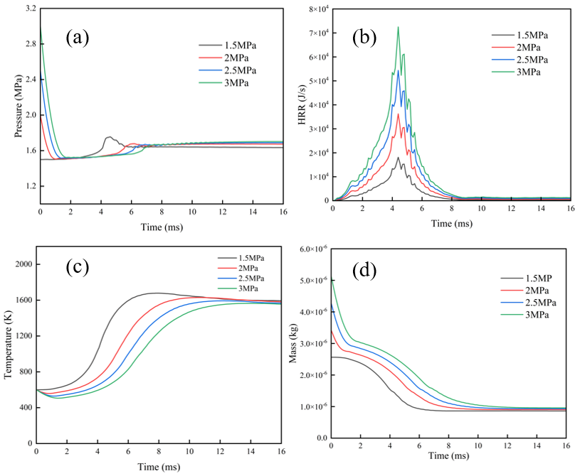
Figure 5a, illustrating the cylinder pressure curves within the pre-chamber, indicates that the overall change in pre-chamber pressure is minimal. As injection pressure increases, the onset of the combustion-induced pressure rise is delayed, consistent with the postponed flame initiation described previously. The observed higher peak pressure at the 1.5 MPa condition is likely attributable to less fuel being ejected into the main chamber at lower pressures, consequently resulting in a lower maximum combustion pressure within the pre-chamber. Based on the heat release rate curves for the pre-chamber under different injection pressures shown in Figure 5b, a comprehensive analysis indicates that the start of heat release and the time to reach the peak heat release rate are largely consistent across pressures. This suggests that increasing the injection pressure does not alter the initial combustion event within the pre-chamber. However, the magnitude of the heat release rate at any given moment increases with higher injection pressure. The peak heat release rate rises significantly from 18,000 J/s at 1.5 MPa to 73,000 J/s at 3.0 MPa, representing a substantial enhancement. Based on the in-chamber temperature curves for the pre-chamber under different injection pressures shown in Figure 5c, the final temperatures are largely similar. However, the onset of the temperature rise is delayed with increasing injection pressure. The highest peak temperature occurs at the 1.5 MPa condition, which is attributed to the same reason stated previously: less fuel is ejected into the main chamber at lower pressures, resulting in more fuel being consumed within the pre-chamber during combustion. To verify complete combustion within the pre-chamber, Figure 5d shows the remaining hydrogen mass in the pre-chamber under different injection pressures.
3.1.3. Analysis of Main Combustion Chamber Parameters
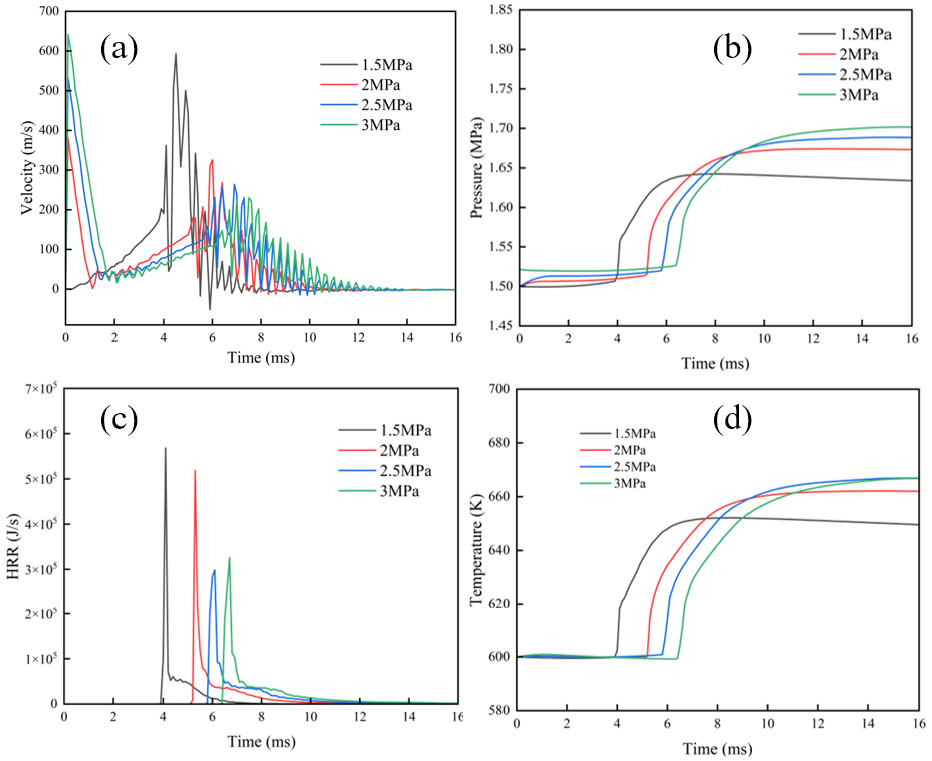
The preceding analysis compared the development of jet flames within the pre-chamber. The following section analyzes flame propagation inside the main combustion chamber. This analysis begins with a comparison of the fluid velocity at the exit of the nozzle orifices to further elucidate the development of jet flames under different injection pressures. The jet velocity curves at the orifice for different injection pressures, shown in Figure 6a, reveal distinct characteristics. Since the main chamber pressure is set at 1.5 MPa, no initial velocity surge occurs at the 1.5 MPa injection pressure. In contrast, for injection pressures of 2.0, 2.5, and 3.0 MPa, an initial velocity surge is observed, the magnitude of which increases with injection pressure. However, this surge subsides within 2 ms. As corroborated by the temperature contours mentioned earlier, no jet flame has formed during this initial period, confirming that no jet flame enters the main chamber at this stage. Furthermore, the slope of the secondary velocity rise decreases with increasing injection pressure. This phenomenon indicates that the secondary velocity peak diminishes and its occurrence is delayed at higher pressures, leading to a reduced jet flame propagation speed. This observation directly validates the previous conclusion that higher injection pressures delay the entry of the jet flame into the main chamber. Additionally, the latter part of the velocity curves aligns with the earlier finding that increased injection pressure prolongs the duration of the jet flame. Analysis of the main chamber cylinder pressure curves under different injection pressures in Figure 6b shows that higher injection pressures delay the pressure rise onset, yet result in higher post-jet combustion pressure, indicating improved ignition effectiveness. This further confirms the previous conclusions that increased injection pressure delays jet flame entry into the main chamber while extending the jet flame duration. Analysis of the main chamber heat release rate curves in Figure 6c reveals that as injection pressure increases from 1.5 MPa to 2.5 MPa, the peak heat release rate gradually decreases, while the width of the high heat release rate region progressively expands. However, this trend does not continue from 2.5 MPa to 3.0 MPa, where the high heat release rate region even narrows slightly. Furthermore, with increasing injection pressure, the initiation of the heat release rate rise is progressively delayed, the timing of the peak shifts later, and the duration from onset until the rate approaches zero increases significantly. These observed characteristics in the curve behavior are consistent with the previously summarized conclusion that higher injection pressures delay the jet flame’s entry into the main chamber and prolong the jet flame duration. Analysis of the main combustion chamber temperature curves under different injection pressures in Figure 6d shows that as the injection pressure increases from 1.5 MPa to 2.5 MPa, the temperature rise initiation is delayed, while the peak temperature increases. However, when pressure is further raised from 2.5 MPa to 3.0 MPa, although the temperature rise is similarly delayed, the peak temperature remains unchanged. This indicates that increasing pressure beyond 2.5 MPa does not yield significant benefits, confirming that 2.5 MPa is more suitable as the injection pressure than 3.0 MPa.
Based on the comprehensive analysis of the four injection pressures investigated in this section, while the highest pressure of 3.0 MPa yields the longest duration and highest peak heat release rate, the jet flame’s entry into the main chamber is excessively delayed without a significant increase in peak temperature, and its duration is prolonged. From the perspectives of efficiency and energy consumption, this may hinder the timely completion of the ignition task. However, the performance gains achieved by increasing the injection pressure from 1.5 MPa to 2.5 MPa are more favorable and worthwhile. Therefore, the optimal injection pressure for this hydrogen jet ignition device is determined to be approximately 2.5 MPa. Subsequent analysis will focus on investigating the operational performance at this injection pressure of 2.5 MPa under varying working temperatures.
3.2. Comparison of Jet Flames under Different Working Temperatures
As identified in Section 3.1, an injection pressure of 2.5 MPa yields the most favorable jet flame characteristics for this ignition device. This chapter will therefore focus on the injection pressure of 2.5 MPa and, following the approach of Meng et al. [22] for different working temperatures, compare the development of jet flames under varying temperature conditions. The specific parameters are listed in Table 4.
Parameters.
|
Items |
Parameter |
|---|---|
|
injection pressure |
2.5 MPa |
|
working temperatures |
600 K, 700 K, 800 K |
3.2.1. Temperature Analysis
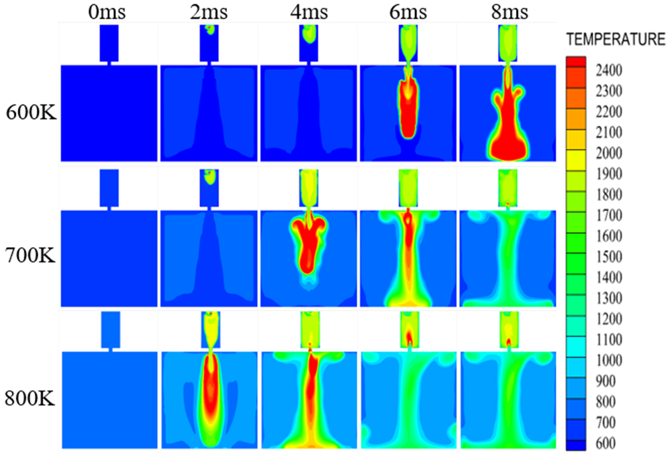
Based on the analysis in Section 3.1.1, at a 600 K working temperature, flame propagates within the pre-chamber within 4 ms after ignition. From 6 ms onward, it passes through the jet orifices into the main chamber as a jet flame, continuing ignition until 12 ms. Comparison of temperature contours at 700 K and 600 K (Figure 7) shows similar early flame behavior at 2 ms. However, by 5 ms, the 700 K flame has already filled most of the pre-chamber and entered the main chamber, forming a higher-temperature, elongated jet flame with roll-up confined to the orifice region—suggesting that increased working temperature may suppress trailing-edge roll-up. By 7 ms, the jet flame at 700 K shows significant decay, whereas at 600 K it persists until 12 ms. This indicates that higher working temperature enhances mixture reactivity, leading to faster ignition, higher peak temperature, but shorter jet flame duration. At 800 K, these effects are more pronounced: nearly half of the pre-chamber mixture is ignited within 1 ms, compared to 3 ms at 700 K and 5 ms at 600 K. By 2 ms, most pre-chamber mixture is combusted, forming a high-energy jet flame with minimal edge roll-up that penetrates deeply into the main chamber. Roll-up remains limited to near the orifices, further confirming the influence of working temperature on flame morphology. By 6 ms, the jet flame has nearly vanished, indicating the end of the jet ignition process. In summary, at 800 K, jet flame development is rapid, but brief total ignition lasts 5 ms, with the jet flame itself sustained for only 3 ms. At 700 K, total ignition time is 7 ms, with jet flame duration slightly over 4 ms and a higher peak temperature than at 800 K. Excessively short ignition duration at 800 K may offer limited advantage over direct spark ignition and could risk incomplete combustion or flame quenching in lean mixtures.
3.2.2. Pre-Ignition Chamber Parameter Analysis
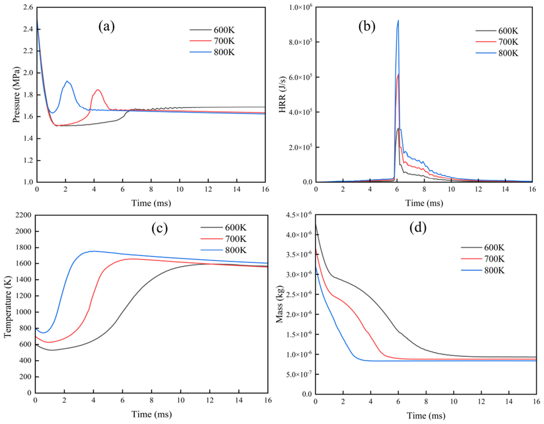
Analysis of the pre-chamber cylinder pressure curves under different working temperatures in Figure 8a shows that the final pressure remains largely unchanged despite temperature variations. However, as the working temperature increases, both the peak combustion pressure and the rate of pressure rise are significantly enhanced. These observations align with the previous conclusion that elevated working temperatures advance combustion initiation and increase the peak combustion pressure. The pre-chamber heat release rate curves under different working temperatures in Figure 8b indicate that the peak heat release rate increases significantly with elevated working temperatures, while the initiation and completion timings remain largely consistent. This demonstrates that increasing the working temperature substantially enhances the heat release rate in the pre-chamber without significantly affecting the overall combustion duration. With pre-chamber temperature curves under different working temperatures in Figure 8c reveal that the final temperature remains largely unaffected by variations in working temperature. However, with increasing working temperature, the onset of the temperature rise occurs earlier, and the peak temperature value is elevated. This observation further confirms that higher working temperatures advance combustion initiation and shorten the combustion process. To verify complete combustion within the pre-chamber, Figure 8d shows the remaining hydrogen mass in the pre-chamber under different injection pressures.
3.2.3. Analysis of Main Combustion Chamber Parameters
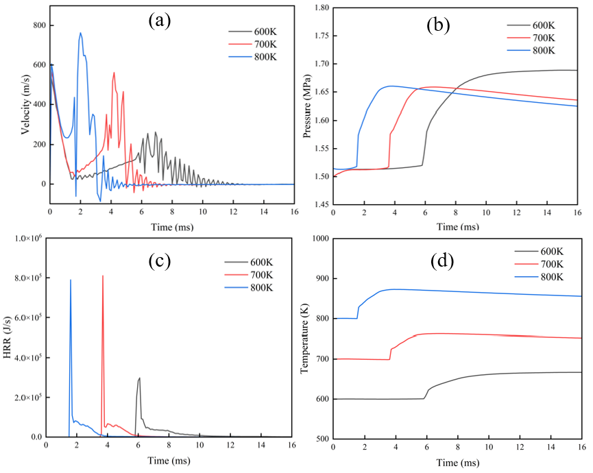
Analysis of the jet flame propagation process is now conducted using parameters from the main combustion chamber. The jet orifice exits velocity curves under different working temperatures in Figure 9a show that as the working temperature increases, the peak exit velocity rises significantly and the time required to reach this peak shortens. Concurrently, the time for the velocity to return to zero is substantially reduced. This confirms that elevating the working temperature indeed accelerates the jet process. The main combustion chamber cylinder pressure curves under different working temperatures in Figure 9b indicate that the final pressure decreases with increasing working temperature. Lower cylinder pressure facilitates flame propagation within the main chamber. Furthermore, both the initiation of pressure changes and the time to reach stabilization occur significantly faster at elevated temperatures, demonstrating an accelerated jet flame ignition process. These observations are consistent with the conclusions drawn previously. Comparison of the main combustion chamber heat release rate curves under different working temperatures in Figure 9c reveals that higher working temperatures significantly shorten both the initiation and completion of heat release. The peak heat release rate, however, reaches its maximum at 700 K. This suggests the optimal working temperature is approximately 700 K, confirming the previous conclusion that elevated temperatures accelerate the jet flame propagation process while reducing its duration. The main combustion chamber temperature curves under different working temperatures in Figure 9d lead to the same conclusion as previously stated.
This section analyzed phenomena through temperature contours, validated observations by comparing jet orifice velocity curves, and examined heat release rate curves across different working temperatures. The results demonstrate that increasing the working temperature accelerates jet flame formation and the ignition process. Consequently, after comprehensive consideration, the optimal working temperature for the jet ignition device operating at an injection pressure of 2.5 MPa is determined to be approximately 700 K.
4. Conclusions
Hydrogen jet ignition is an important means of enhancing ignition in difficult-to-ignite conditions; studying its flame propagation process is vital to the development of jet ignition devices. This study focuses on investigating the characteristics of jet flames in a hydrogen jet ignition device. Primarily examines the development trends of the hydrogen jet flame under different injection pressures. After identifying a suitable injection pressure, the influence of different working temperatures on jet flame development is investigated. The results are then compared and summarized. The main conclusions are as follows:
(1) As injection pressure increases, the formation of the jet flame is delayed, and its duration is prolonged. The peak temperature and peak heat release rate of the jet flame increase.
(2) As working temperature increases, the formation time of the jet flame is significantly shortened, and its duration is substantially reduced. The roll-up structures of the jet flame are attenuated, while its heat release rate is enhanced.
The findings suggest that for hydrogen jet ignition systems operating under lean conditions, an injection pressure of 2.5 MPa and a working temperature around 700 K can achieve an optimal balance between ignition timing and flame stability, providing practical guidance for pre-chamber design in hydrogen engines. In future work, we will focus on pre-chamber ignition systems for internal combustion engines and conduct systematic experimental investigations to validate their performance.
Author Contributions
Y.G.: data curation, writing—original draft preparation; G.Z.: visualization, investigation; W.C.: supervision; Y.W.: software, validation; Q.Z.: writing—reviewing and editing. All authors have read and agreed to the published version of the manuscript.
Funding
This research was funded by the projects of the Guangxi Science and Technology Major Program (GuikeAA24206057), the China Postdoctoral Science Foundation (2023MD734160), the Scientific Research Fund of Hunan Provincial Education Department (24B0156), the Natural Science Foundation of Hunan Province (2023JJ50240 and 2025JJ70096) and the Guangxi Postdoctoral Special Foundation (2023011 and 2024053).
Institutional Review Board Statement
Not applicable for studies not involving humans or animals.
Informed Consent Statement
Not applicable for studies not involving humans.
Data Availability Statement
The original contributions presented in this study are included in the article. Further inquiries can be directed to the corresponding authors.
Acknowledgments
This work is supported by the projects of the Guangxi Science and Technology Major Program (GuikeAA24206057), the China Postdoctoral Science Foundation (2023MD734160), the Scientific Research Fund of Hunan Provincial Education Department (24B0156), the Natural Science Foundation of Hunan Province (2023JJ50240 and 2025JJ70096), and the Guangxi Postdoctoral Special Foundation (2023011 and 2024053).
Conflicts of Interest
The authors declare no conflict of interest.
Use of AI and AI-assisted Technologies
No AI tools were utilized for this paper.
References
- 1.
Zhang, C.; Sun, B.; Wang, X.; Chai, H. Direct-Injection Hydrogen Jet Characteristics of Outward-Opening Nozzle. Automot. Engine 2020, 04, 7–12+24.
- 2.
Cheng, H.; Wang, Q.; Zhao, C. Ignition characteristics of natural gas/hydrogen jet diffusion collision flame. China Sci. 2018, 13, 2636–2642.
- 3.
Biswas, S.; Qiao, L. Ignition of ultra-lean premixed hydrogen/air by an impinging hot jet. Appl. Energy 2018, 228, 954–964.
- 4.
Li, G. Research on the Impact of Injection Strategies on Combustion and Emissions of Hydrogen/Gasoline Dual-Fuel Engines. Ph.D. Thesis, Jilin University, Changchun, China, 2022.
- 5.
Chen, M. Experimental and Simulation Study on Supersonic Hydrogen Jet from Rectangular Nozzles. Master’s Thesis, Shandong University, Jinan, China, 2020.
- 6.
Mendez, L.A.; Tummers, M.J.; Van Veen, E.H.; Roekaerts, D.J.E.M. Effect of hydrogen addition on the structure of natural-gas jet-in-hot-coflow flames. Proc. Combust. Inst. 2015, 35, 3557–3564.
- 7.
Wang, N.; Liu, J.; Chang, W.L.; Lee, C.-F.F. Ignition kinetics of a homogeneous hydrogen/air mixture using a transient hot jet. Int. J. Hydrogen Energy 2018, 43, 16373–16385.
- 8.
Feng, Z. Research on the Influence of Turbulent Jet Ignition in the Pre-Combustion Chamber on the Combustion Characteristics of Natural Gas Engines. Master’s Thesis, Tianjin University, Tianjin, China, 2023.
- 9.
Xu, X. The Influence of Direct ignition and Jet Ignition in the Pre-Ignition Chamber on the Temperature and Pressure Increase of a Large-Bore Constant Volume. Master’s Thesis, Shanghai Jiao Tong University, Shanghai, China, 2023.
- 10.
Xiangtan University. Green Intelligent Manufacturing Research Institute of Xiangtan University, Foshan. A Hydrogen Jet Ignition Device. CN202221081955.0, 13 September 2022.
- 11.
Wang, J. Simulation Study on Thermal Jet Characteristics of High-Energy Ignition System in Pre-Combustion Chamber. Master’s Thesis, Jilin University, Changchun, China, 2023.
- 12.
Stadler, A.; Wessoly, M.; Blochum, S.; Härtl, M.; Wachtmeister, G. Gasoline Fueled Pre-Chamber Ignition System for a Light-Duty Passenger Car Engine with Extended Lean Limit. SAE Int. J. Engines 2019, 12, 323.
- 13.
Stadler, A.; Sauerland, H.; Härtl, M.; Wachtmeister, G. The Potential of Gasoline Fueled Pre-Chamber Ignition Combined with Elevated Compression Ratio. SAE Tech. Pap. 2020, 2020, 12.
- 14.
Attard, W.P.; Blaxill, H. A Gasoline Fueled Pre-Chamber Jet Ignition Combustion System at Unthrottled Conditions. SAE Int. J. Engines 2012, 5, 315–329.
- 15.
Müller, C.; Pischinger, S.; Tews, S.; Müller, A.; Habermann, K. Analysis of experimental results with an active pre-chamber ultra-lean burn SI engine. Int. J. Engine Res. 2021, 22, 3103–3127.
- 16.
Zhu, S.; Akehurst, S.; Lewis, A.; Yuan, H. A review of the pre-chamber ignition system applied on future low-carbon spark ignition engines. Renew. Sustain. Energy Rev. 2022, 154, 1364–0321.
- 17.
Liu, Y.; Gong, Y.; Jincheng, L.; Chen, H.E. Research and Development Prospects of Gasoline Engine Pre-ignition Chamber Technology. Automot. Dig. 2019, 11, 11–15.
- 18.
Zhu, G.; Wang, Y.; Zuo, Q.; Chen, W.; Shen, Z.; Yang, X.; Kou, C.; Ning, D.; Wang, H. Numerical investigation gaseous ammonia basic jet and mixing characteristics in the constant volume vessel. Int. J. Hydrogen Energy 2024, 80, 68–81.
- 19.
Zhang, X.; Tian, J.; Cui, Z.; Xiong, S.; Yin, S.; Wang, Q.; Long, W. Visualization study on the effects of pre-chamber jet ignition and methane addition on the combustion characteristics of ammonia/air mixtures. Fuel 2023, 338, 127204.
- 20.
Wang, Y. Research on Ammonia Injection Characteristics and Jet Ignition Combustion Process. Master’s Thesis, Xiangtan University, Xiangtan, China, 2024. (In Chinese)
- 21.
Meng, X.; Zhao, C.; Cui, Z.; Zhang, X.; Zhang, M.; Tian, J.; Long, W.; Bi, M. Understanding of combustion characteristics and NO generation process with pure ammonia in the pre-chamber jet-induced ignition system. Fuel 2023, 331, 125743.
- 22.
Meng, X.; Zhao, C.; Qin, M.; Zhang, M.; Dong, D.; Long, W.; Bi, M. Study on chemical kinetics and NO behaviors in pre-chamber jet-induced ignition mode with ammonia. Fuel Process. Technol. 2023, 250, 107876.


This work is licensed under a Creative Commons Attribution 4.0 International License.
 Suite 4002 Level 4, 447 Collins Street, Melbourne, Victoria 3000, Australia
 General Inquiries: info@sciltp.com