Based on a three-dimensional simulation platform, this study investigated the effects of N2, CO2, and O2 as dilution gases on the combustion and emission performance of methanol engines under constant total fuel quantity, dilution ratio of 10%/20%, and blending ratio of 0%/10%/20% conditions. In terms of combustion performance, diluting the syngas can shorten the ignition delay period and combustion duration, advance the combustion center, increase the peak cylinder pressure and temperature, and the effect is most significant when CO2 is diluted (for example, in the 20% dilution ratio CO2 condition, the 20% blending ratio is 3.5 °CA shorter than 0%); the ignition delay period and combustion duration become longer, the cylinder pressure decreases under CO2 conditions, and slightly increases under N2 and O2 conditions. In terms of emission performance, NOX emissions are CO2 < N2 < O2 (at a 10% dilution ratio and 10% blending ratio, CO2 relative to O2 reduces NOX by 98.5%); under O2 conditions, syngas blending reduces CO emissions, while under N2 and CO2 conditions, it increases, and under CO2 with a 20% dilution ratio, CO sharply increases; syngas blending reduces the emissions of HC, CH3OH, and CH2O, and under O2 dilution, the CO emissions are the lowest, and they increase as the dilution ratio increases. In summary, N2 dilution is beneficial for the coordinated optimization of combustion and NOX emissions.
- Open Access
- Article
Study on the Effect of Diluted Gas on the Lean Combustion Performance of Methanol-Diluted Gas Engines
- Hao Gong 1,
- Fangxi Xie 1,
- Hangshi Qu 2,
- Dingchao Qian 2,
- Jiaquan Duan 2,
- Beiping Jiang 1,*,
- Xiangyang Wang 1
Author Information
Received: 08 Dec 2025 | Revised: 31 Mar 2026 | Accepted: 07 Apr 2026 | Published: 11 May 2026
Abstract
1. Introduction
Carbon neutrality is currently a common global development goal [1,2]. The transportation sector is a key field for achieving the global carbon neutrality strategy, among which exploring and applying alternative fuels is one of the core paths to reduce carbon emissions [3,4]. With the maturity of CO2 catalytic hydrogenation to methanol technology [5,6], methanol’s fuel characteristics have transformed from a low-carbon fuel to a renewable carbon-neutral fuel. For traditional internal combustion engine vehicles, the main emissions from burning gasoline include CO, HC, NOX, and other particulate matter [7,8]. At this point, methanol shows significant advantages as a clean alternative fuel [9,10]. As an ideal oxygenated alternative fuel, it has long been a research focus due to its efficient, clean combustion technology [11]. For methanol engines, in-depth research on the blending of methanol engine cracked gas is of great significance for improving their comprehensive performance.
Diluted combustion technology refers to reducing the pumping and heat losses in gasoline engines by increasing the excess air ratio, thereby improving thermal efficiency [12]. Its main method of optimizing the combustion process is to introduce lean combustion working fluid into the intake air on the basis of stable equivalence ratio combustion [13,14]. However, when the mixture is too lean, it will lead to combustion instability and even misfire [15]. Through in-depth research on natural gas engines, Wang [16] discussed the multiple benefits of exhaust gas recirculation (EGR) technology. Its core mechanism lies in introducing part of the exhaust gas into the cylinder, which not only reduces the peak combustion temperature by diluting the oxygen concentration and increasing the specific heat capacity of the mixture to avoid problems such as peak heat waste, but also significantly suppresses knock and reduces NOX emissions without significantly affecting combustion stability. Liu [17] discussed the impact of different dilution strategies on engine combustion, comprehensively compared the effects of exhaust gas recirculation and excess air ratio on combustion and emissions, and found that compared with pure air dilution, EGR dilution has stronger combustion regulation capabilities and can better balance the contradiction between thermal efficiency and NOX emissions. Wang et al. [18] studied the impact of different types of dilution gases on the combustion of methanol engines, comprehensively compared the influence laws of various gases on engine combustion and emissions, and found that compared with N2, CO2 has a stronger inhibitory effect on combustion and can better balance thermal efficiency and emissions.
Cracked gas is a hydrogen-rich gas produced by the catalytic cracking of methanol, mainly composed of H2, CO, and a small amount of CH4 [19]. It can not only inherit the advantages of hydrogen but also avoid the difficulties of hydrogen storage and transportation, providing a reliable fuel for engines [20]. Hua et al. [21] found that blending cracked gas with high reactivity and high flame propagation speed can effectively improve the ignition characteristics and combustion rate of lean mixtures, enabling the engine to maintain a stable combustion process under a higher excess air ratio. It not only expands the combustion limit but also significantly reduces NOX emissions due to more complete combustion and lower peak temperature. Yao et al. [22] explored the impact of simulated methanol cracked gas blending on methanol engine performance through CONVERGE three-dimensional simulation and experiments. Their research found that blending methanol-cracked gas has little impact on engine power performance while improving engine thermal efficiency. Increasing the methanol cracked gas substitution ratio leads to an increase in peak cylinder pressure and peak heat release rate, along with an advance in the corresponding crankshaft angle, a forward shift of the combustion center, and a shortening of the combustion duration.
In summary, both cracked gas blending and diluted combustion technology are effective methods to improve the lean combustion performance of methanol engines. This paper will use simulation methods to study the effects of different cracked gas blending ratios on the combustion and emission characteristics of cracked gas-blended methanol engines under diluted combustion conditions, providing data support for the development of methanol engines.
2. Experimental Setup and Methods
2.1. Construction of the Simulation Model
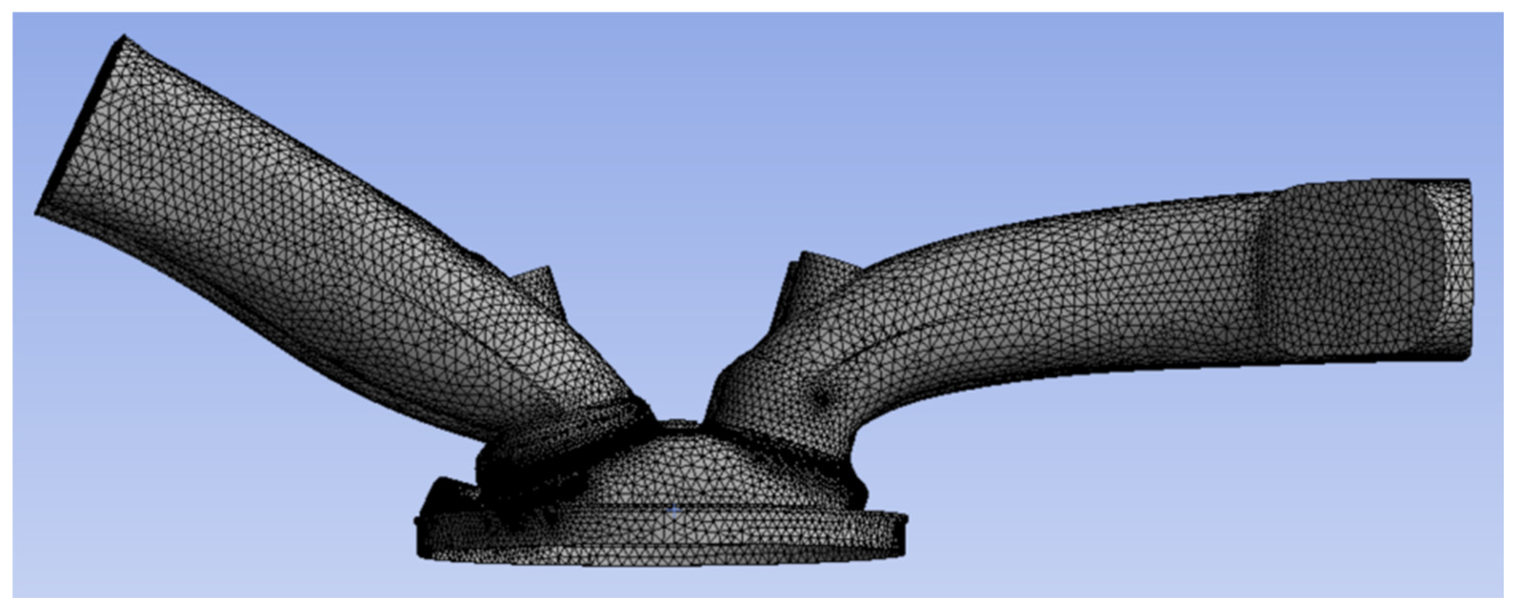
The engine simulation model used in this study was established based on a four-cylinder, four-stroke turbocharged spark-ignition engine adopted in the test bench, which has a displacement of 2.0 L, a compression ratio of 11.2, and is equipped with dual variable valve timing (VVT) for intake and exhaust as well as an EGR system. The mesh generation diagram of the engine geometric model is shown in Figure 1.
There are three types of initial boundaries in this study, namely moving boundaries, flow boundaries, and fixed boundaries. Among them, the piston top and intake/exhaust valves are set as moving boundaries: the movement of the piston top is synchronized with the measured movement curve, and the movement of the intake/exhaust valves is directly determined by the valve lift data. The flow boundaries include the inlet of the intake port and the outlet of the exhaust port, which are designated as the inlet boundary and outlet boundary, respectively. All other boundaries are set as fixed boundaries. Table 1 shows the temperature settings of the fixed boundaries. These temperature settings fully consider the actual operating temperature distribution of each component, ensuring the reliability of the simulation results.
Temperature settings of fixed boundaries.
|
Boundary Name |
Temperature |
|---|---|
|
Top Surface of the Chamber |
500 K |
|
Upper Surface of the Piston |
500 K |
|
Cylinder Liner Surface |
450 K |
|
Exhaust Port Surface |
550 K |
|
Exhaust Port Surface |
340 K |
|
Bottom Surface of the Intake Valve |
480 K |
|
Bottom Surface of the Exhaust Valve |
525 K |
2.2. Validation of the Simulation Model
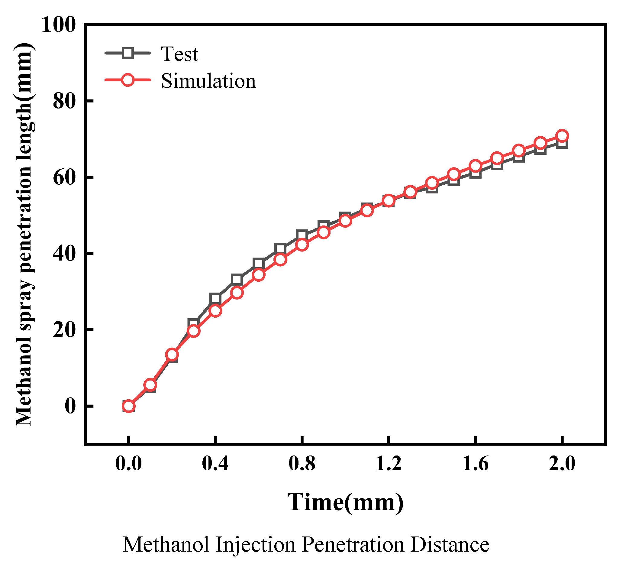
All three-dimensional simulation models adopted in this study have been validated. First, the methanol spray was calibrated. Calibration and validation were performed based on the methanol spray penetration distance and cracked gas jet penetration distance tested on the visual constant-volume bomb research platform. Figure 2 shows the validation of the methanol injection model. The simulation results are basically consistent with the experimental data, with an error within 5%. This proves that the methanol spray model can accurately predict the spray characteristics of the direct-injection methanol six-hole injector in the cylinder in this study. The validation conditions for methanol injection are an injection pressure of 10 MPa and a background pressure of 0.1 MPa.
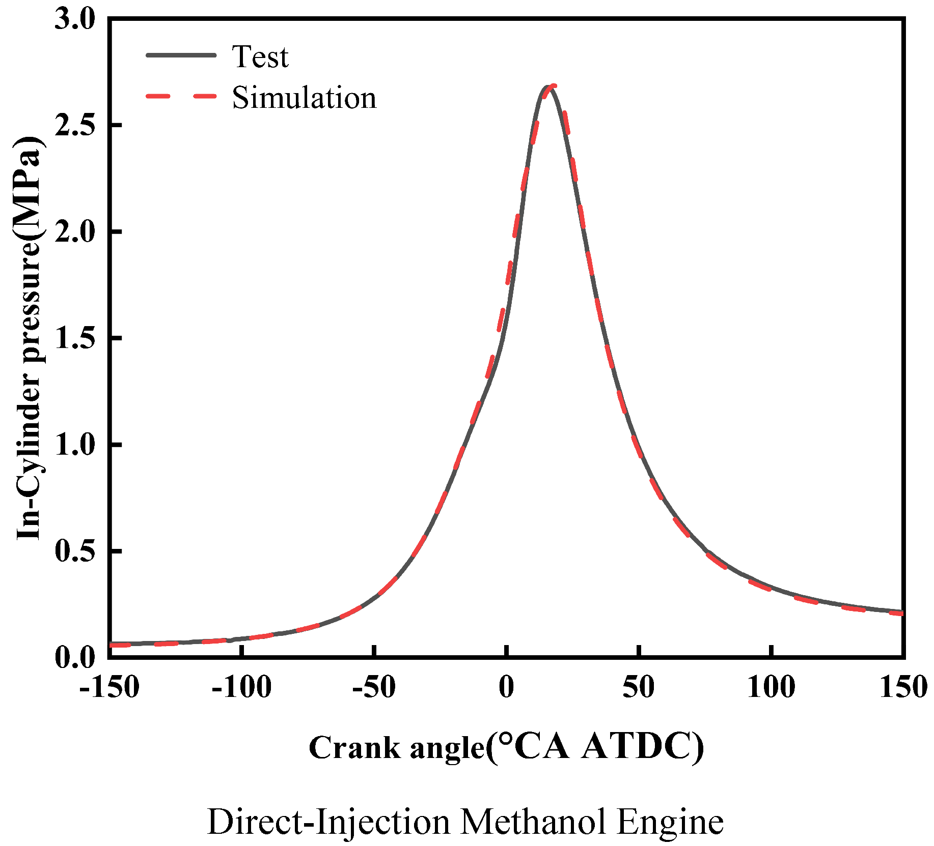
Second, this study validated two simulation models: the direct-injection cracked gas coupled with intake port-injected methanol engine model, and the direct-injection methanol coupled with intake port-injected cracked gas engine model. Validation was conducted based on the in-cylinder pressure curves measured on the corresponding thermodynamic engine test bench. Specifically, Figure 2 presents the calibration and validation results of the methanol injection model, primarily verifying the spray characteristics, while Figure 3 shows the in-cylinder pressure validation results for the two simulation models mentioned above. The in-cylinder pressure curves obtained from simulation calculations are basically consistent with those from experiments, maintaining a high degree of fitting. Through the validation presented in Figure 2 and Figure 3, the accuracy of both the spray model and the overall engine combustion model is ensured. Validation was conducted based on the in-cylinder pressure curves measured on the corresponding thermodynamic engine test bench. The in-cylinder pressure curves obtained from simulation calculations are basically consistent with those from experiments, maintaining a high degree of fitting.
Figure 3 shows the validation of the three-dimensional engine simulation model. For the validation of the direct-injection methanol engine simulation model, the difference in peak in-cylinder pressure between experimental and simulation data is 0.01 MPa, with a corresponding crankshaft angle difference of 1.5 °CA. From the above verification, the difference in peak in-cylinder pressure between experiment and simulation does not exceed 2%, and the corresponding crankshaft angle difference does not exceed 2 °CA. It can be concluded that the direct-injection methanol engine models established in this study are relatively accurate and can reliably calculate the engine combustion performance.
2.3. Research Scheme
This study investigates the effect of methanol cracked gas blending ratio on engine combustion performance under the following conditions: engine speed of 1500 r/min, total fuel mass of 25.3 mg, injection timing of 270°BTDC, and injection pressure of 35 MPa. During the simulation, N2, CO2, and O2 are used as diluents. While maintaining a constant total fuel mass, the cracked gas blending ratios are set to 0%, 10%, and 20%. To eliminate the impact of intake pressure changes on in-cylinder combustion, comparative studies are conducted under two constant volume dilution ratios (10% and 20%). The combustion performance and emission performance of the methanol engine are analyzed to clarify the influence of cracked gas blending on the lean-burn performance of the methanol engine.
The cracked gas blending ratios and volume dilution ratios are shown in Table 2. In this study, the cracked gas blending ratio is defined as the proportion of energy contributed by the cracked gas to the total fuel energy, with the total fuel energy input kept constant across all operating conditions.
Cracked gas blending ratios and volume dilution ratios.
|
Cracked Gas Blending Ratio |
Volume Dilution Ratio |
Type of Diluent |
|---|---|---|
|
0% |
10%, 20% |
N2, CO2, O2 |
|
10% |
10%, 20% |
N2, CO2, O2 |
|
20% |
10%, 20% |
N2, CO2, O2 |
3. Comprehensive Performance Analysis of Experimental Results
3.1. Combustion Performance
Figure 4 illustrates the influence of diluent gases on combustion parameters under different cracked gas blending ratios. As shown in Figure 4, under the same dilution ratio and diluent gas, with the increase of cracked gas blending ratio, both the ignition delay period and combustion duration are shortened. Meanwhile, the effect of cracked gas blending on the combustion parameters of methanol engines is more significant when the diluent gas is CO2 compared with N2 and O2. Specifically, when the dilution ratio is 20% and the diluent is CO2, the effect of cracked gas blending on ignition delay period, combustion duration, and combustion center of gravity is the most obvious. At this time, compared with the cracked gas blending ratio of 0%, the ignition delay period and combustion duration at the blending ratio of 20% are shortened by 3.5 °CA and 13.5 °CA, respectively, and the combustion center of gravity is advanced by 8.5 °CA. This indicates that cracked gas blending can improve the combustion performance of methanol engines under different diluent gases. To verify the uniformity of the in-cylinder mixture, the spatial distribution of the equivalence ratio and the mole fractions of cracked gas components (H2 and CO) were analyzed at the spark timing.
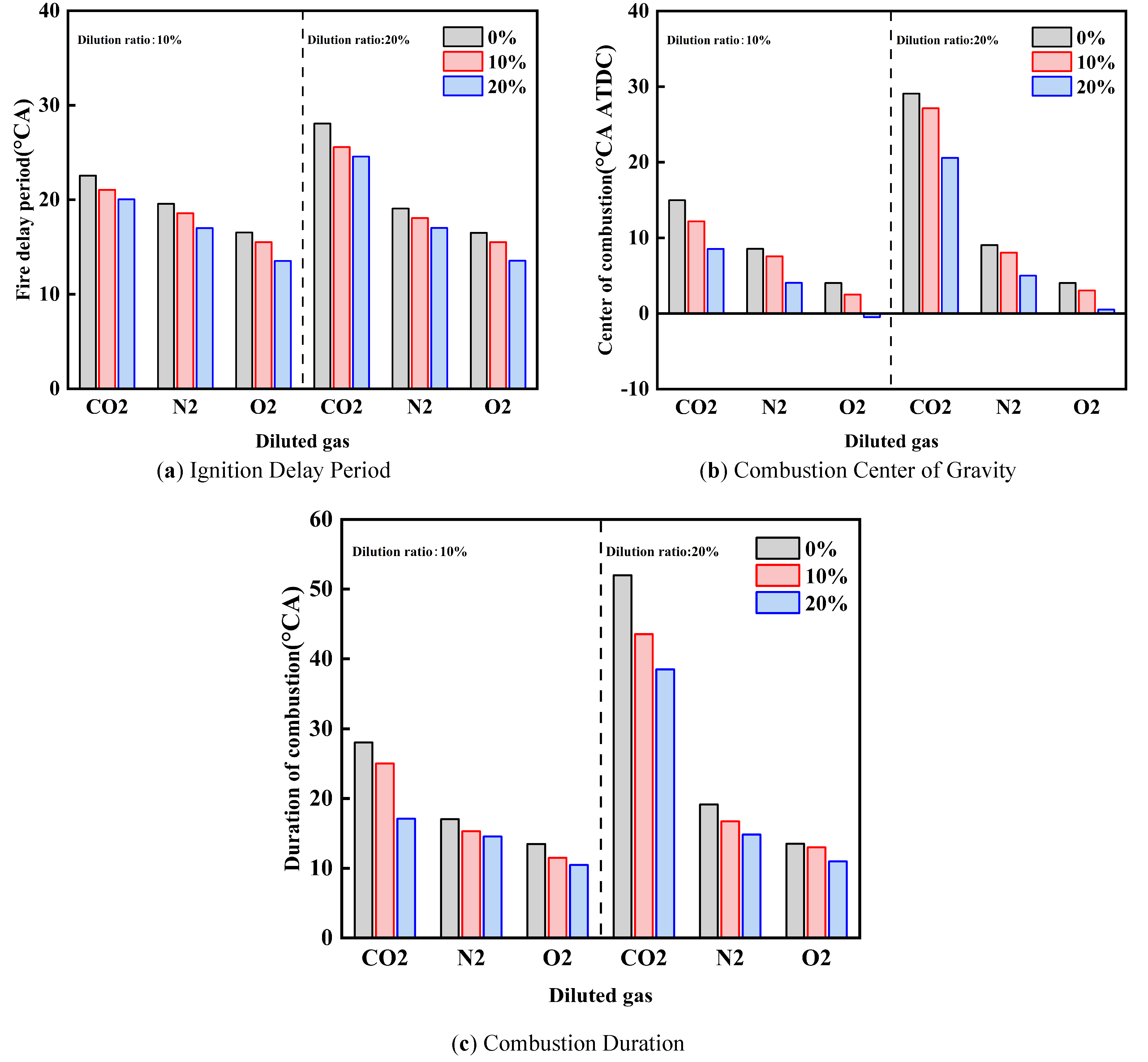
Under the same dilution ratio and cracked gas blending ratio, when the diluent gas is CO2, the ignition delay period and combustion duration are shorter, and the combustion center of gravity is the most retarded, followed by N2 and O2. With the increase of dilution ratio, the influence of diluent gas on ignition delay period, combustion duration, and combustion center of gravity becomes more significant. Taking the cracked gas blending ratio of 0% as an example, when the dilution ratio is 10%, compared with O2, the ignition delay periods of CO2 and N2 are prolonged by 6.0 °CA and 2.6 °CA respectively, the combustion durations are prolonged by 14.6 °CA and 3.6 °CA respectively, and the combustion centers of gravity are advanced by 11.0 °CA and 4.5 °CA respectively. When the dilution ratio is 20%, the ignition delay periods are prolonged by 11.6 °CA and 3.0 °CA, respectively; the combustion durations are prolonged by 38.5 °CA and 5.6 °CA, respectively; and the combustion centers of gravity are advanced by 25.0 °CA and 5.0 °CA, respectively. In terms of in-cylinder specific heat capacity, the order is CO2 > N2 > O2. Meanwhile, CO2 is a product of the methanol combustion reaction and can inhibit the methanol reaction; N2 does not participate in the methanol combustion reaction, while O2 is a reactant of the methanol combustion reaction and can promote the reaction. Therefore, when the diluent gas is CO2, the ignition delay period and combustion duration are the shortest, and the combustion center of gravity is the most retarded, followed by N2 and O2. When the dilution ratio increases, the effect of diluent gas on combustion temperature and combustion reaction is enhanced; thus, the influence of diluent gas on ignition delay period, combustion duration, and combustion center of gravity becomes more obvious with the increase of dilution ratio.
Under the same diluent gas and cracked gas blending ratio, with the increase of dilution ratio, the ignition delay period and combustion duration are prolonged, and the combustion center of gravity is retarded. When the cracked gas blending ratio is 10%, for the diluent gases CO2, N2, and O2, the ignition delay periods at the dilution ratio of 20% are prolonged by 4.5 °CA, 0.5 °CA, and 0.2 °CA, respectively, compared with those at 10%. The combustion durations are prolonged by 18.5 °CA, 1.5 °CA, and 1.0 °CA, respectively, and the combustion centers of gravity are retarded by 15.0 °CA, 0.5 °CA, and 0.4 °CA, respectively. This is because with the increase of dilution ratio, the mass of in-cylinder working fluid increases, resulting in the decrease of combustion temperature and combustion speed. Therefore, the ignition delay period and combustion duration are prolonged, and the combustion center of gravity is retarded.
Figure 5 shows the effect of diluent gases on the in-cylinder pressure of cracked gas blended engines. Under the same dilution ratio and diluent gas, with the increase of cracked gas blending ratio, the peak in-cylinder pressure increases and the corresponding crankshaft angle advances. Taking a dilution ratio of 10% as an example, when the diluent gases are CO2, N2, and O2, the peak in-cylinder pressure at a cracked gas blending ratio of 20% increases by 0.85 MPa, 0.45 MPa, and 0.43 MPa, respectively, compared with that at 0%. Since cracked gas blending can affect combustion processes under all three diluent gases, it can also increase the peak in-cylinder pressure for these three gases.
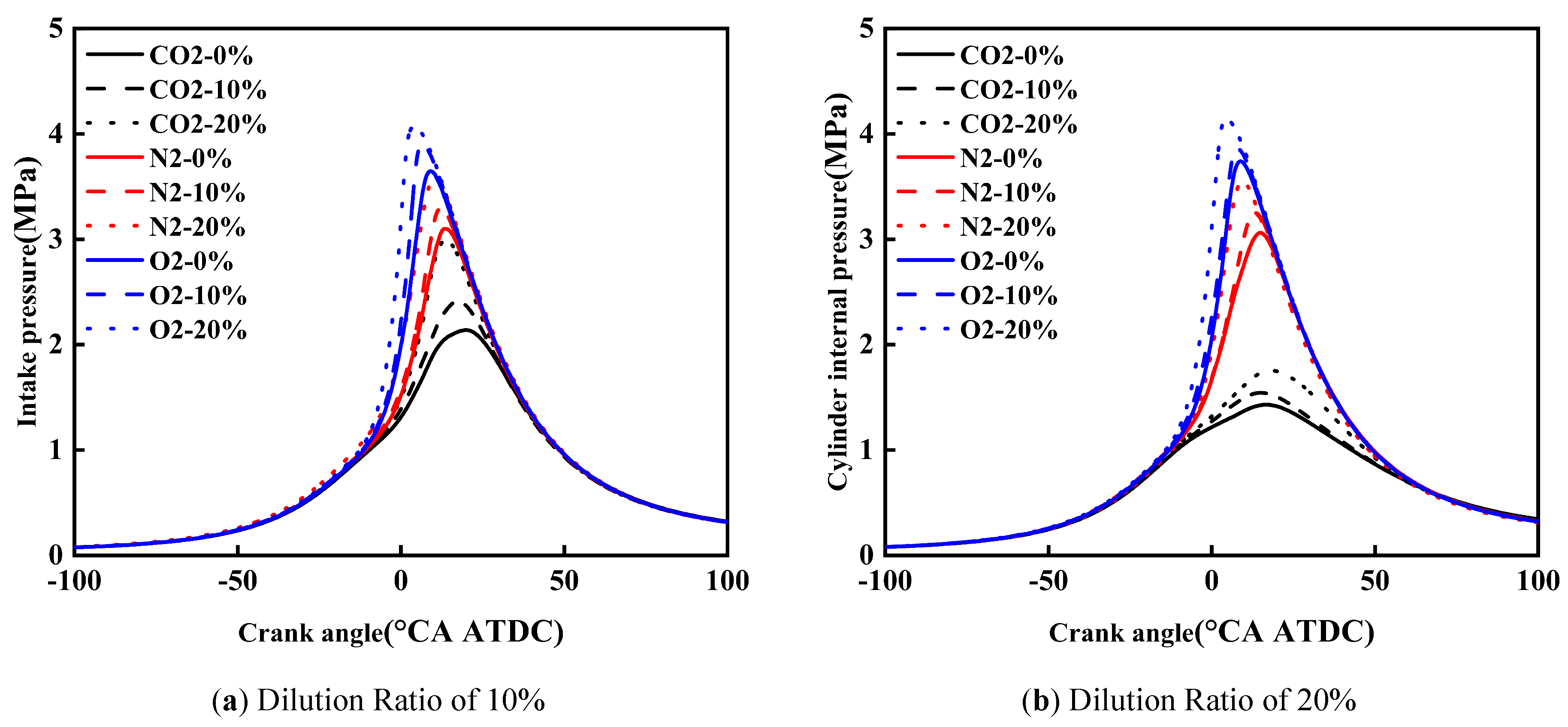
Under the same dilution ratio and cracked gas blending ratio, the peak in-cylinder pressure follows the order: O2 > N2 > CO2. Taking a dilution ratio of 10% and a cracked gas blending ratio of 10% as an example, the peak in-cylinder pressure of O2 and N2 is 1.5 MPa and 0.9 MPa higher than that of CO2 respectively. This is because when CO2 is used as the diluent gas, the ignition delay period and combustion duration are the short, and the combustion center of gravity is the most retarded, followed by N2 and O2.
At the same cracked gas blending ratio, when CO2 is the diluent gas, the peak in-cylinder pressure decreases with the increase of dilution ratio. However, when N2 and O2 are the diluent gases, the peak in-cylinder pressure increases slightly as the dilution ratio rises. Taking a cracked gas blending ratio of 20% as an example, for diluent gases CO2, N2, and O2, the peak in-cylinder pressure at a dilution ratio of 20% decreases by 1.24 MPa, increases by 0.02 MPa, and increases by 0.07 MPa respectively compared with that at 10%. When CO2 is the diluent gas, the increase in dilution ratio leads to a significant prolongation of the ignition delay period and combustion duration, thus resulting in a decrease in peak in-cylinder pressure. In contrast, the increase in dilution ratio has little effect on the ignition delay period and combustion duration when N2 and O2 are used as diluent gases. Meanwhile, the increase in dilution ratio leads to an increase in the mass of in-cylinder working fluid. Therefore, when N2 and O2 are the diluent gases, the increase in dilution ratio causes a slight rise in peak in-cylinder pressure.
Constant volume specific heat capacity refers to the heat required for a unit mass of substance to raise its temperature by 1 K under the condition of constant volume. During the combustion process of spark-ignition engines, the in-cylinder volume change is small, so constant volume specific heat capacity is an important factor affecting the in-cylinder combustion temperature. Figure 6 shows the effect of diluent gases on the constant volume specific heat capacity of cracked gas blended engines. It can be seen from the figure that in the initial stage of the ignition process, the constant volume specific heat capacity increases with the increase of the cracked gas blending ratio, which is due to the fact that the constant volume specific heat capacity of cracked gas is higher than that of methanol. For different diluent gases, it can be seen that the effect of diluent gases on the constant volume specific heat capacity is small; it is basically the same when the dilution ratio is 10%, while O2 is slightly lower than CO2 and N2 when the dilution ratio is 20%. Therefore, it can be determined that from the perspective of physical properties, the effects of the three gases on the in-cylinder combustion temperature are significantly different. Comparing the constant volume specific heat capacity of the in-cylinder gas under different dilution ratios, it is found that the constant volume specific heat capacity is also not significantly different with the increase of the dilution ratio.
Figure 7 shows the effect of diluent gases on the total mass of in-cylinder working fluid of cracked gas blended engines. Under the same volume dilution ratio, the total mass of in-cylinder working fluid with CO2 as the diluent gas is greater than that with O2, which is greater than that with N2. At the same time, the total mass of in-cylinder working fluid increases with the increase of the dilution ratio. From the perspective of physical properties, the inhibition of in-cylinder temperature by diluent gases and dilution ratio mainly comes from the increase of in-cylinder working fluid mass rather than the properties of diluent gases.
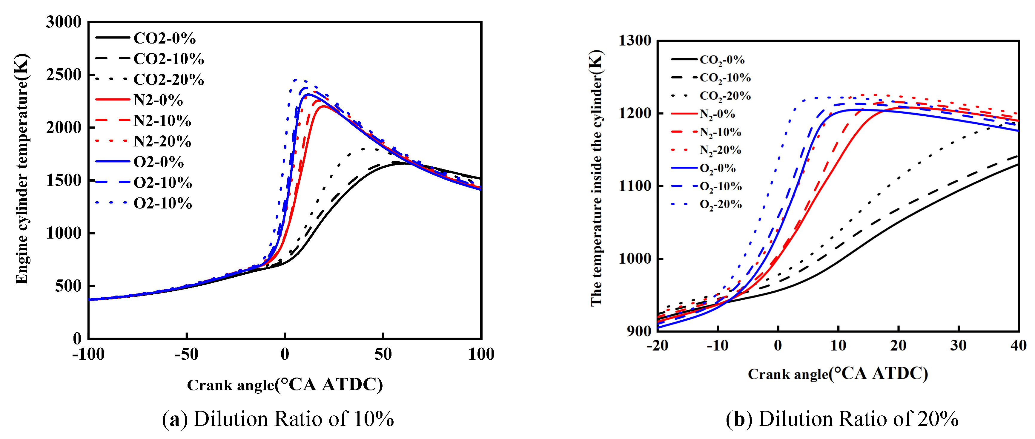
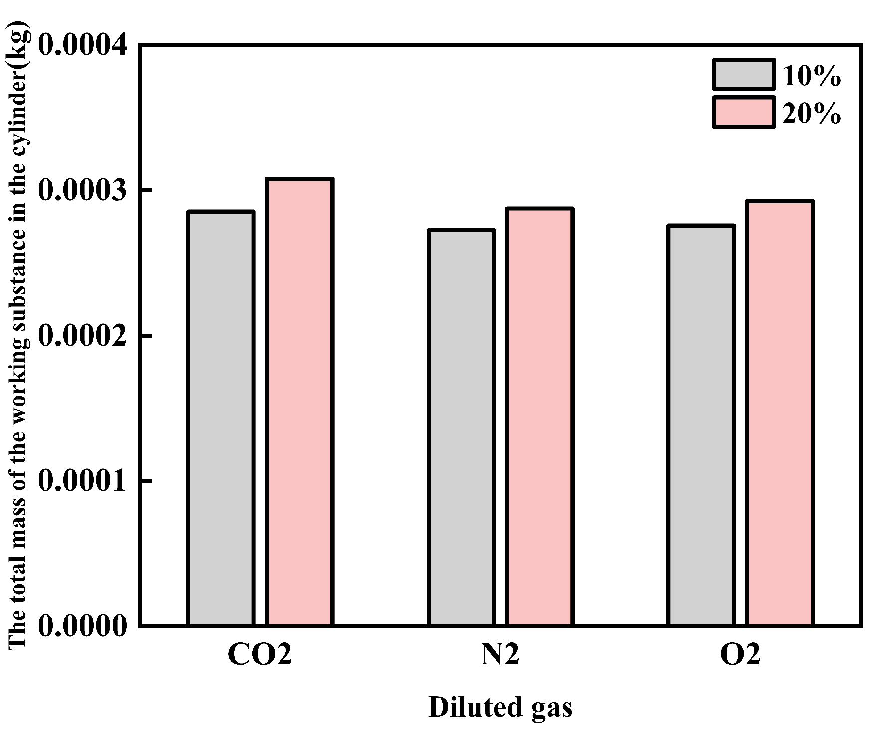
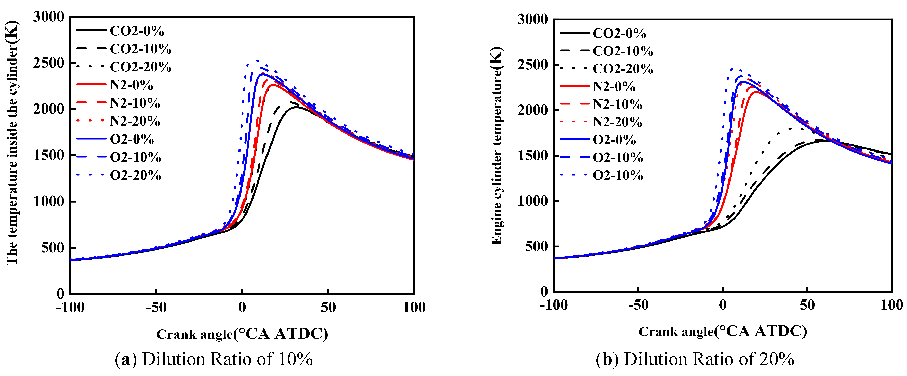
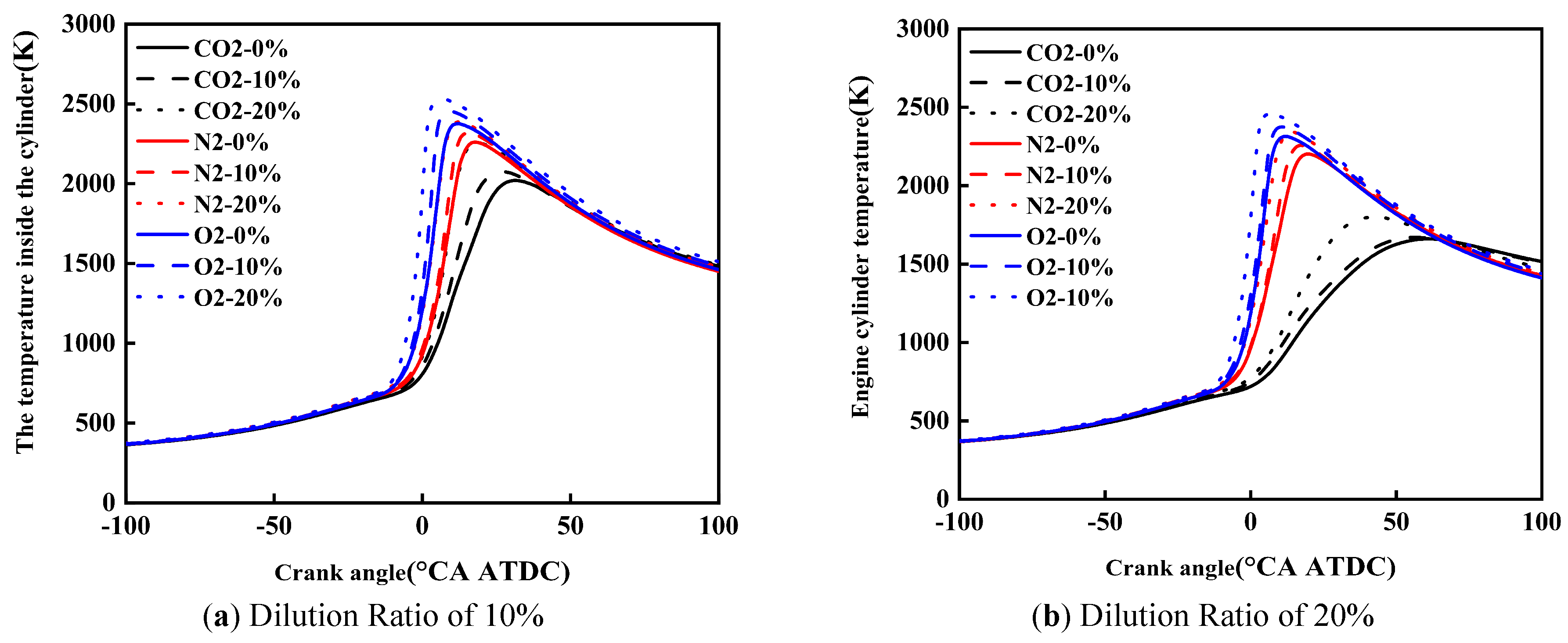
Figure 8 shows the effect of diluent gases on the in-cylinder temperature of cracked gas blended engines. Under the same dilution ratio and diluent gas, with the increase of the cracked gas blending ratio, the peak in-cylinder temperature rises and the corresponding crankshaft angle advances. Taking a dilution ratio of 10% as an example, when the diluent gases are CO2, N2, and O2, the peak in-cylinder temperature increases by 237 K, 127 K, and 154 K, respectively. This is because although the blending of cracked gas leads to an increase in the constant volume specific heat capacity of the in-cylinder working fluid, it is obvious that the acceleration of combustion rate caused by cracked gas blending is more significant. Therefore, cracked gas blending can result in an increase in the peak in-cylinder temperature.
Under the same dilution ratio and cracked gas blending ratio, the peak in-cylinder temperature follows the order: O2 > N2 > CO2. Taking a dilution ratio of 10% and a cracked gas blending ratio of 10% as an example, the peak in-cylinder temperature of O2 and N2 is 243 K and 380 K higher than that of CO2, respectively. This is because the effect of diluent gases on the constant volume specific heat capacity is small, but when CO2 is used as the diluent gas, the ignition delay period and combustion duration are the shortest, and the combustion center of gravity is the most retarded, followed by N2 and O2. In this study, methanol is directly injected into the cylinder using a high-pressure direct injection system. Specifically, the cracked gas is supplied from high-pressure cylinders and injected into the intake manifold via a dedicated electronically controlled gas injector, where it mixes with the intake air before entering the cylinder. Similarly, the dilution gases are introduced into the intake manifold through a separate injection system and are premixed with the intake air upstream of the intake port. To ensure mixture homogeneity, the injection of cracked gas and dilution gases is continuously controlled during the intake stroke, allowing sufficient time for mixing with the intake air before entering the cylinder. The intake manifold is designed to promote turbulent mixing, and the in-cylinder flow field further enhances mixture uniformity during the compression stroke. This configuration ensures that the cracked gas and dilution gases are uniformly distributed in the cylinder before combustion.
2.2. Emission Performance and Sources
Figure 9 shows the effect of diluent gases on the NOX emissions of cracked gas blended engines. As shown in Figure 9a, under the same dilution ratio and cracked gas blending ratio, the NOX increase emissions follow the order: CO2 < N2 < O2. Taking a cracked gas blending ratio of 10% and a dilution ratio of 10% as an example, the NOX emissions of CO2 and N2 are 98.5% and 89.3% lower than that of O2, respectively. This is mainly attributed to the difference in in-cylinder combustion temperature, where the combustion temperature of CO2 is lower than that of N2, which is lower than that of O2. The cracked gas used in this study is a hydrogen-rich gas produced by catalytic cracking of methanol. It was not generated online during engine operation but was obtained from a separate methanol cracking experimental setup. The composition of the cracked gas was maintained consistent across all simulation conditions.
As shown in Figure 9b, under the same CA50, comparing the engine NOX emissions of different diluent gases, it is found that the NOX emissions of O2 are significantly higher than those of CO2 and N2, while the difference between CO2 and N2 is small. The CA50 and NOX emissions are basically the same under the conditions of CO2 with a dilution ratio of 10% and a cracked gas blending ratio of 20%, and N2 with a dilution ratio of 20% and a cracked gas blending ratio of 10%. However, when the dilution ratio is 10%, the CA50 is basically the same for O2 with a cracked gas blending ratio of 0% and N2 with a cracked gas blending ratio of 20%, but the NOX emissions differ greatly. This is because O2 directly participates in the formation reaction of NOX, and the increase in O2 promotes the generation of NOX emissions. It is worth noting that when the cracked gas blending ratio is 0%, and O2 is the diluent gas, the CA50 changes slightly as the dilution ratio increases from 10% to 20%, while the NOX emissions show a slight downward trend. Once beyond this range, the further promoting effect of continuing to increase the dilution ratio on NOX emissions is obviously weakened.
An optimized application analysis of the cracked gas blending ratio and diluent gas is carried out for Figure 9b. It can be seen that under the same dilution ratio and cracked gas blending ratio, CO2 achieves the optimal NOX emissions, and N2 achieves the coordinated optimization of NOX emissions and combustion performance.
Figure 10 shows the effect of diluent gases on the CO emissions of cracked gas blended engines. Under different diluent gases, the influence of the law of cracked gas blending on engine CO emissions varies. When O2 is the diluent gas, cracked gas blending can significantly reduce CO emissions, while the effect is opposite when N2 and CO2 are used as diluent gases. Specifically, at a dilution ratio of 10%, with CO2, N2, and O2 as diluent gases, respectively, the CO emissions at a cracked gas blending ratio of 20% increase by 51.4%, 53.0%, and decrease by 84.2% compared with those at 0%. Figure 11 shows the effect of diluent gases on the in-cylinder CO formation region distribution of cracked gas blended engines. The results indicate that there are significant differences in the CO distribution regions under different diluent gases. When N2 and CO2 are the diluent gases, the in-cylinder CO distribution region is relatively wide, while when O2 is the diluent gas, CO is mainly distributed in the wall region. This suggests that when N2 and CO2 are used as diluent gases, CO emissions are mainly affected by the distribution of rich and lean fuel regions in the cylinder, while under O2 dilution, the CO formation region is similar to that of HC emissions. Therefore, as the cracked gas blending ratio increases, the base amount of in-cylinder CO increases, leading to a rise in CO emissions when N2 and CO2 are the diluent gases. In contrast, when O2 is the diluent gas, the in-cylinder combustion temperature increases, resulting in a decrease in CO emissions.
A further comparison of CO emissions under different diluent gases reveals that the engine CO emissions with O2 as the diluent gas are much lower than those with N2 and CO2. At a dilution ratio of 10%, the CO emission levels of CO2 and N2 are similar, but when the dilution ratio increases to 20%, the CO emissions with CO2 as the diluent gas are significantly higher than those with N2. This is because the cylinder is in an oxygen-rich state when O2 is the diluent gas; the engine CO emissions with O2 are much lower than those with N2 and CO2. When N2 and CO2 are the diluent gases, CO emissions are mainly affected by the in-cylinder combustion temperature. At a dilution ratio of 10%, the combustion temperatures under the two diluent gases are not significantly different, leading to similar CO emission levels. However, when the dilution ratio increases to 20%, CO2 dilution causes obvious combustion deterioration due to excessively slow combustion speed and significantly reduced combustion temperature, which in turn triggers a sharp rise in CO emissions. It is worth noting that when N2 and O2 are the diluent gases, the CO emissions change gently with the increase of the dilution ratio. But when CO2 is the diluent gas, the CO emissions increase significantly as the dilution ratio rises. This indicates that when the combustion temperature and speed drop below a certain threshold, CO emissions will increase sharply.
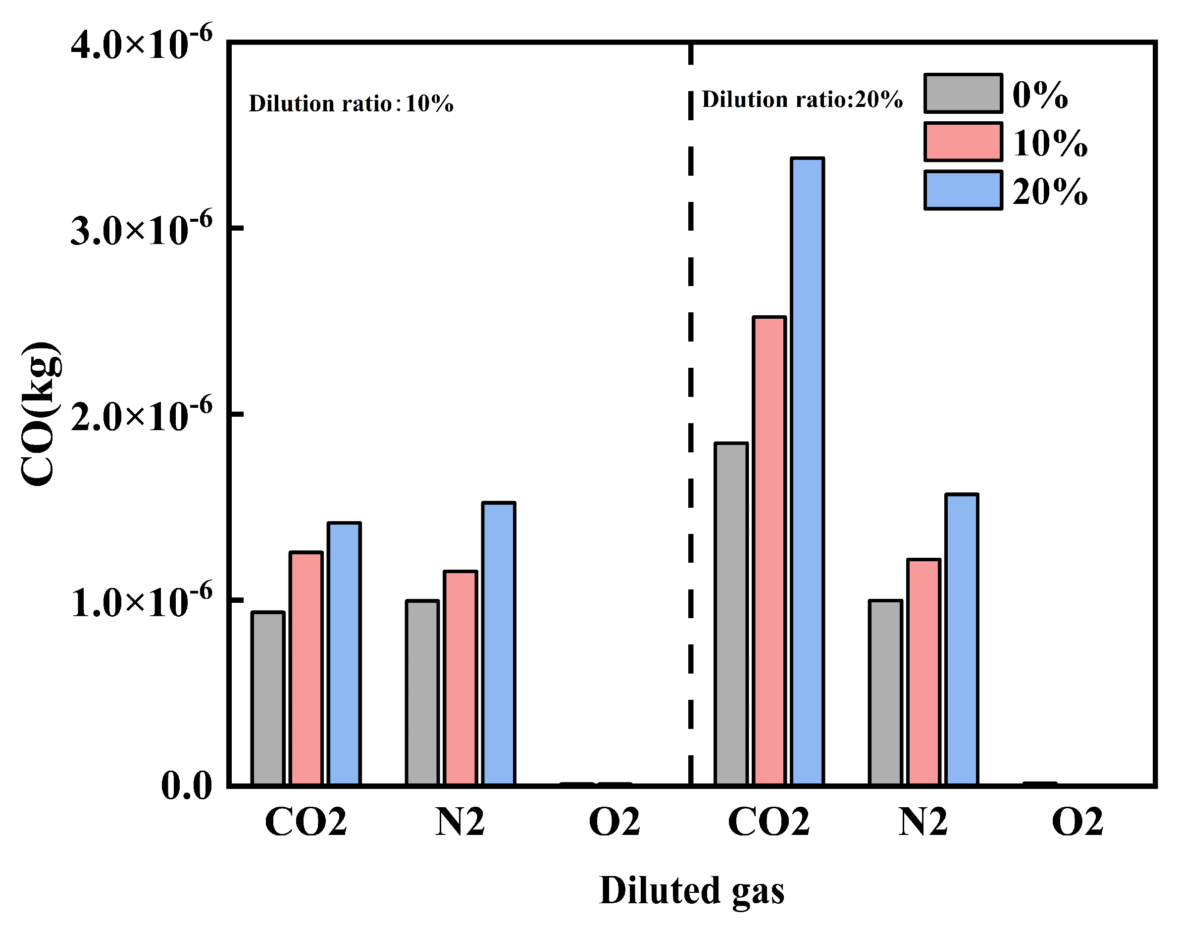
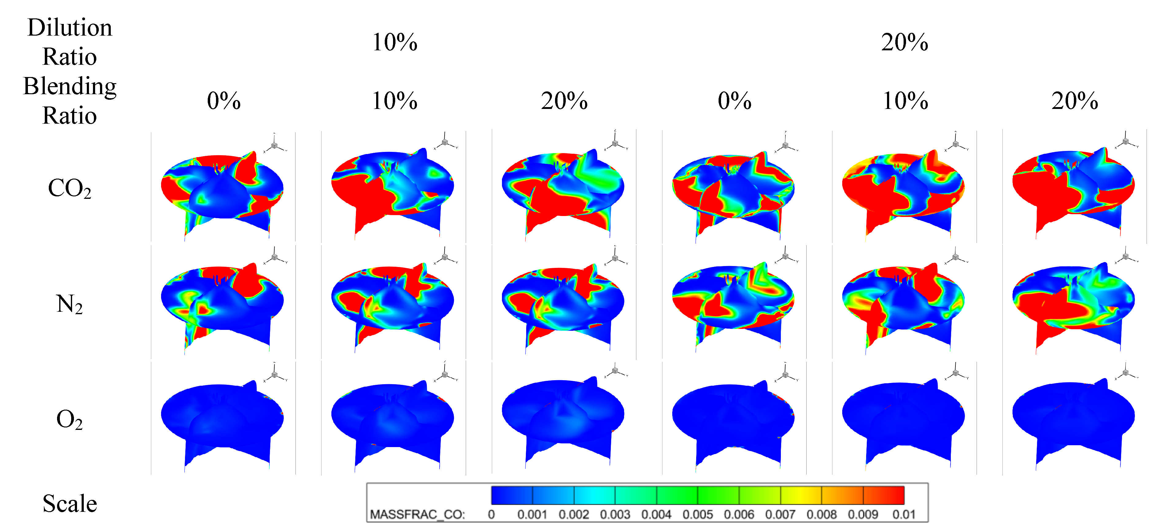
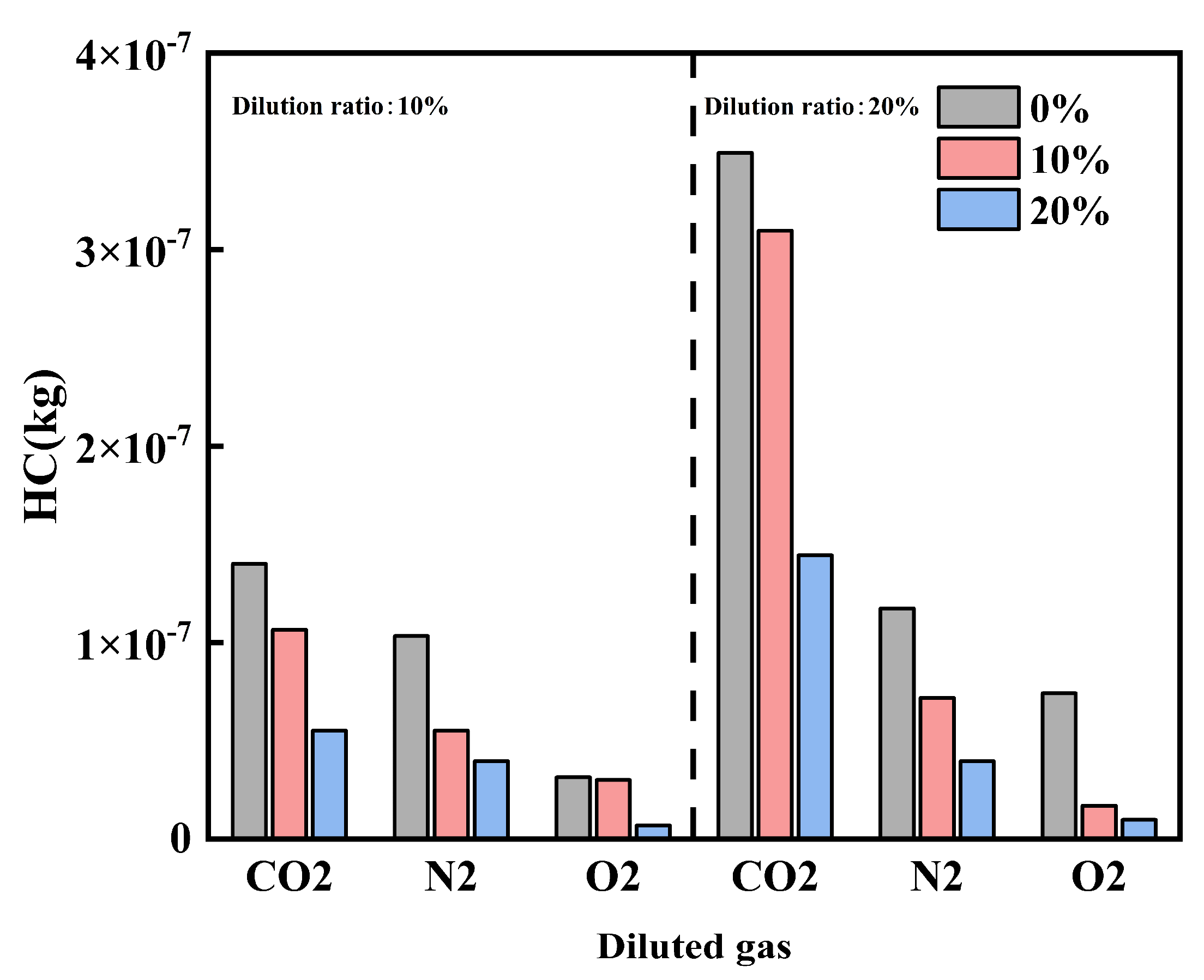
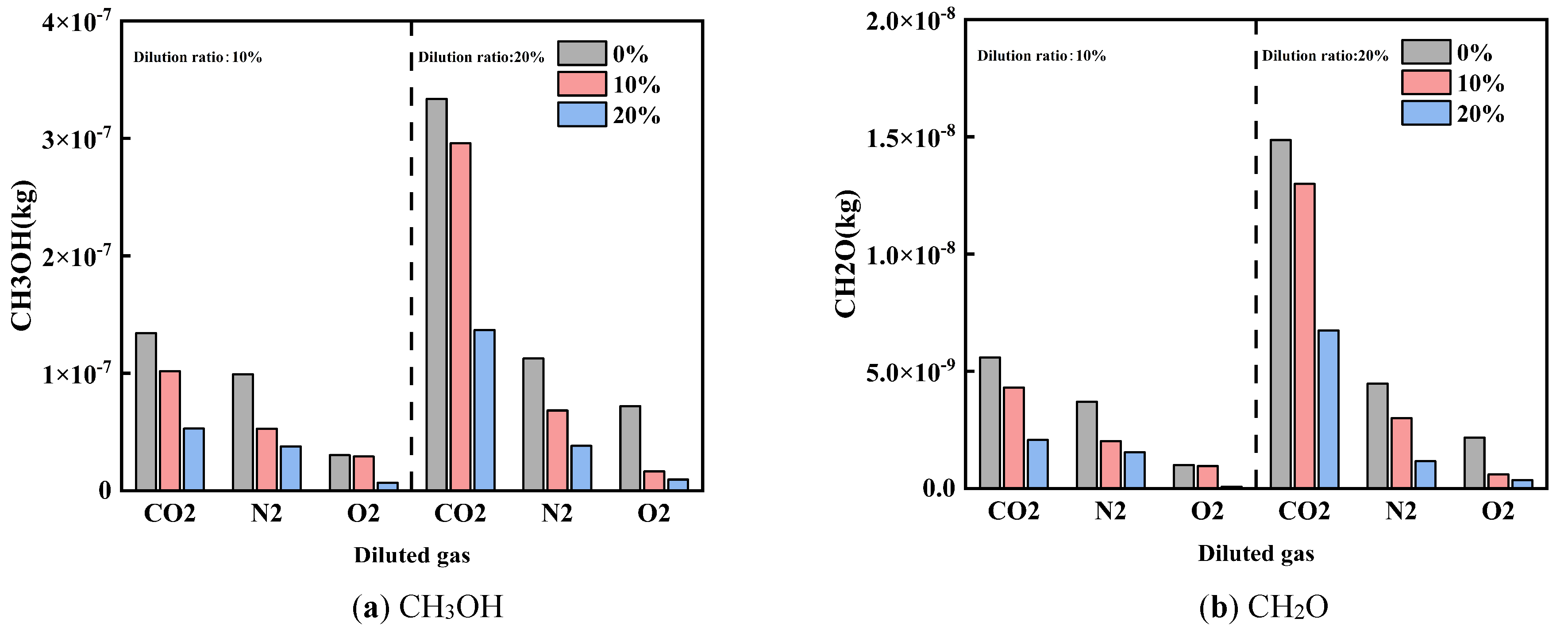
Figure 12 and Figure 13 show the effects of diluent gases on HC emissions and unconventional emissions under different cracked gas blending ratios, respectively. Studies have shown that regardless of the type of diluent gas used, blending cracked gas can effectively reduce HC, CH3OH, and CH2O emissions. At a dilution ratio of 20%, with CO2, N2, and O2 as diluent gases respectively, the HC emissions at a cracked gas blending ratio of 20% are reduced by 58.7%, 66.3%, and 86.8% compared with those at 0%; the CH3OH emissions are reduced by 59.0%, 66.0%, and 86.9% respectively; and the CH2O emissions are reduced by 54.8%, 73.9%, and 83.8% respectively. This is mainly because cracked gas blending can increase the in-cylinder combustion temperature, thereby weakening the wall quenching effect and further reducing HC, CH3OH, and CH2O emissions.
Further analysis reveals that there are differences in the effects of diluent gases on HC and unconventional emissions. Comparing the effects of different diluent gases on HC and unconventional emissions, the emission levels follow the order: O2 < N2 < CO2. This result is related to the changes in in-cylinder combustion temperature caused by different diluent gases. At the same time, as the dilution ratio increases, both HC and unconventional emissions increase. This is because the in-cylinder combustion temperature decreases with the increase of the dilution ratio.
4. Summary
This study systematically investigates the effects of different diluent gases (CO2, N2, O2) combined with cracked gas blending on the combustion and emission characteristics of methanol engines. The main conclusions are as follows:
Cracked gas blending can effectively promote the combustion process, significantly shorten the ignition delay period and combustion duration, and advance the combustion center of gravity. This optimization effect is most pronounced under CO2 dilution and high dilution ratio conditions. Compared with other diluent gases, CO2 exhibits the strongest inhibitory effect on combustion due to its high specific heat capacity and chemical inhibition; O2 achieves the highest in-cylinder pressure and temperature by promoting reactions.
The NOX emission level follows the order of CO2 < N2 < O2. Cracked gas blending can reduce CO emissions under O2 dilution, but leads to increased CO emissions under N2 and CO2 dilution—especially at high CO2 dilution ratios, where CO emissions rise sharply. In addition, cracked gas blending can effectively reduce HC, CH3OH, and CH2O emissions, with the lowest concentrations of these pollutants observed under O2 dilution.
Overall, N2 dilution shows excellent potential in achieving the coordinated optimization of engine combustion performance and NOX emissions. Meanwhile, the strong inhibitory characteristics of CO2 indicate its unique value in specific applications requiring combustion temperature control.
The results of this study can provide a theoretical basis and data support for the future combined application of online methanol cracking technology and methanol lean-burn technology.
The cracked gas produced from the methanol cracking process is typically at a high temperature (approximately 500–600 K). To eliminate the influence of temperature variations on the intake mixture and combustion characteristics, the cracked gas was cooled to ambient temperature (approximately 298 K) using a heat exchanger before being stored in high-pressure cylinders. The cooled cracked gas was then introduced into the intake manifold through a dedicated electronically controlled gas injector, with its injection temperature maintained at the same level as the intake air (approximately 298 K) across all operating conditions. This approach ensures that the observed effects of cracked gas blending on combustion and emissions are solely attributed to its chemical composition and reactivity, rather than temperature-induced variations.
Author Contributions
H.G.: conceptualization, methodology, software, formal analysis, writing—original draft preparation; F.X.: data curation, visualization; H.Q.: investigation, validation; D.Q.: supervision, resources; J.D.: software, validation; B.J.: writing—reviewing and editing, supervision, funding acquisition; X.W.: investigation, data curation. All authors have read and agreed to the published version of the manuscript.
Funding
This work was financially supported by the National Natural Science Foundation (52476117) and the Jilin Provincial Department of Science and Technology (20240301004ZD).
Institutional Review Board Statement
Not applicable.
Informed Consent Statement
Not applicable.
Data Availability Statement
Not applicable.
Conflicts of Interest
The authors declare no conflict of interest.
Use of AI and AI-Assisted Technologies
No AI tools were utilized for this paper.
References
- 1.
Bayraktar, M.; Yuksel, O.; Pamik, M. An evaluation of methanol engine utilization regarding economic and upcoming regulatory requirements for a container ship. Sustain. Prod. Consum. 2023, 39, 345–356. https://doi.org/10.1016/j.spc.2023.05.029.
- 2.
Wang, L.; Xie, F.; Han, L. Research on performance improvement of ammnia engine based on optimization of active pre-chamber hydrogen injection strategy. J. Energy Inst. 2026, 124, 102383. https://doi.org/10.1016/j.joei.2025.102383.
- 3.
Dimitriou, P.; Tsujimura, T. A review of hydrogen as a compression ignition engine fuel. Int. J. Hydrogen Energy 2017, 42, 24470–24486. https://doi.org/10.1016/j.ijhydene.2017.07.232.
- 4.
Zhu, G.; Wang, Y.; Zuo, Q.; Chen, W.; Shen, Z.; Yang, X.; Kou, C.; Ning, D.; Wang, H. Numerical investigation gaseous ammonia basic jet and mixing characteristics in the constant volume vessel. Int. J. Hydrogen Energy 2024, 80, 68–81. https://doi.org/10.1016/j.ijhydene.2024.06.396.
- 5.
Yi, C.; Fang, J.; Xu, X.; Wang, K.; Zuo, Z.; Han, Z. Effect of ash participation on the catalytic activity of as-prepared catalysts to promote diesel soot combustion. J. Energy Inst. 2023, 111, 101407. https://doi.org/10.1016/j.joei.2023.101407.
- 6.
Bicer, Y.; Dincer, I. Life cycle environmental impact assessments and comparisons of alternative fuels for clean vehicles. Resour. Conserv. Recycl. 2018, 132, 141–157. https://doi.org/10.1016/j.resconrec.2018.01.036.
- 7.
Liang, Z.; Xie, F.; Jiang, B.; Li, X.; Su, Y.; Wang, Z. Evaluating the potential of mixture formation methods to achieve efficient combustion and near-zero emissions on a hydrogen direct injection engine. J. Clean. Prod. 2024, 439, 140930. https://doi.org/10.1016/j.jclepro.2024.140930.
- 8.
Liang, Z.; Xie, F.; Guo, Z.; Wang, Z.; Dou, H.; Wang, B.; Shen, B. Optimization and prediction of a novel preignition in hydrogen direct injection engines through experimentation and the Random forest algorithms. Energy Convers. Manag. 2024, 313, 118602. https://doi.org/10.1016/j.enconman.2024.118602.
- 9.
Yapicioglu, A.; Dincer, I. Experimental investigation and evaluation of using ammonia and gasoline fuel blends for power generators. Appl. Therm. Eng. 2019, 154, 1–8. https://doi.org/10.1016/j.applthermaleng.2019.02.072.
- 10.
Waris, U.; Yasin, S. Unveiling the impacts of sustainable digital-green transformation on renewable energy consumption: Driving active sustainability at COP29. J. Environ. Manag. 2025, 395, 128019. https://doi.org/10.1016/J.JENVMAN.2025.128019.
- 11.
Valera-Medina, A.; Xiao, H.; Owen-Jones, M.; David, W.I.F.; Bowen, P.J. Ammonia for power. Prog. Energy Combust. Sci. 2018, 69, 63–102. https://doi.org/10.1016/j.pecs.2018.07.001.
- 12.
Yang, Y.; Wang, Y.; Long, W.; Cui, J.; Dong, P.; Wang, Q.; Chen, W. Synergistic impacts of methanol hydration/reforming on methanol-diesel dual direct injection engine. Energy 2025, 338, 138923. https://doi.org/10.1016/J.ENERGY.2025.138923.
- 13.
Kang, Z.; Peng, D.; Luo, J.; Lv, Y.; Li, L. Effect of structural parameters of active pre-chamber on ammonia/hydrogen premixed combustion process: A numerical investigation. Case Stud. Therm. Eng. 2025, 65, 105687. https://doi.org/10.1016/j.csite.2024.105687.
- 14.
Zhu, S.; Akehurst, S.; Lewis, A.; Yuan, H. A review of the pre-chamber ignition system applied on future low-carbon spark ignition engines. Renew. Sustain. Energy Rev. 2022, 154, 111872. https://doi.org/10.1016/j.rser.2021.111872.
- 15.
Sun, J.; Tang, Q.; Zhu, X.; Wen, M.; Huang, L.; Ming, Z.; Liu, H.; Yao, M. Unlocking ammonia engines: Pre-chamber ignition with partial ammonia cracking. Energy 2025, 335, 137961. https://doi.org/10.1016/j.energy.2025.137961.
- 16.
Wang, Y.; Zhou, X.; Liu, L. Feasibility study of hydrogen jet flame ignition of ammonia fuel in marine low speed engine. Int. J. Hydrogen Energy 2023, 48, 327–336. https://doi.org/10.1016/j.ijhydene.2022.09.198.
- 17.
Liu, J.; Yu, Q.; Cheng, J.; Unguwanrimi Yakubu, A.; Ye, X.; Xiong, S. Numerical study of a cold start at the ambient temperature of 243 K on methanol engine with coolant heating. Fuel 2025, 395, 135138. https://doi.org/10.1016/J.FUEL.2025.135138.
- 18.
Wang, Z.; Qi, Y.; Sun, Q.; Lin, Z.; Xu, X. Ammonia combustion using hydrogen jet ignition (AHJI) in internal combustion engines. Energy 2024, 291, 130407. https://doi.org/10.1016/j.energy.2024.130407.
- 19.
Liu, Z.; Zhou, L.; Zhong, L.; Liu, P.; Wei, H. Experimental investigation on the combustion characteristics of NH3/H2/air by the spark ignition and turbulent jet ignition. Combust. Sci. Technol. 2024, 196, 73–94. https://doi.org/10.1080/00102202.2022.2063687.
- 20.
Rajasegar, R.; Niki, Y.; García-Oliver, J.M.; Li, Z.; Musculus, M.P.B. Fundamental insights on ignition and combustion of natural gas in an active fueled pre-chamber spark-ignition system. Combust. Flame 2021, 232, 111561. https://doi.org/10.1016/j.combustflame.2021.111561.
- 21.
Hua, J.; Zhou, L.; Gao, Q.; Feng, Z.; Wei, H. Influence of pre-chamber structure and injection parameters on engine performance and combustion characteristics in a turbulent jet ignition (TJI) engine. Fuel 2021, 283, 119236. https://doi.org/10.1016/j.fuel.2020.119236.
- 22.
Yao, C.; Li, X.; Xu, Y.; Zang, R. Research on the performance of an electronically controlled spark ignition engine fuelled with hydrogen-rich gases. Proc. Inst. Mech. Eng. Part D J. Automob. Eng. 2014, 228, 1084–1094. https://doi.org/10.1177/0954407014525360.

This work is licensed under a Creative Commons Attribution 4.0 International License.
 Suite 4002 Level 4, 447 Collins Street, Melbourne, Victoria 3000, Australia
 General Inquiries: info@sciltp.com