
As the mainstream power system for unmanned aerial vehicles (UAVs), enhancing the performance of two-stroke engines is of paramount importance. This study developed a computational fluid dynamics (CFD) numerical model of the in-cylinder flow and combustion process in an opposed-piston two-stroke UAV engine. It focused on the influence patterns of rotational speed and injection timing on the engine’s combustion characteristics and power output. Research scenarios were set for typical rotational speed conditions (1000–3000 r/min) and injection timing conditions (−35 to −15 °CA before top dead center, BTDC). Results indicate that overall increasing engine speed while retarding the injection timing yields improved combustion efficiency and power output. At an engine speed of 2000 r/min, the ignition delay is reduced, and with an injection timing of −20 °CA, the engine shows a moderate process of combustion and heat release. Under these operating conditions, the combustion is characterized by a moderate heat release rate, relatively high cylinder pressure, enhanced indicated work and power, and comparatively low cylinder temperatures. Considering all performance aspects, employing an engine speed of 2000 r/min and an injection timing of −20 °CA yields superior combustion and power performance.
- Open Access
- Article
Analysis of Combustion Characteristics and Power Performance of an Opposed-Piston Two-Stroke Unmanned Aerial Vehicles Engine
- Lishan Wang 1,†,
- Yan Li 2,†,
- Xiangen Ke 3,
- Jiajun Yan 1,
- Jinhao Yan 1,
- Ziyuan Zou 1,
- Wei Chen 1,*
Author Information
Received: 03 Apr 2026 | Revised: 07 May 2026 | Accepted: 08 May 2026 | Published: 29 May 2026
Abstract
Keywords
unmanned aerial vehicle | two-stroke engine | opposed-piston engine | rotational speed | injection timing
1. Introduction
With the spread of applications for unmanned aerial vehicles (UAVs) in aerial photography, agriculture, security, logistics, etc., they have shown good flexibility and cost-effectiveness. However, electric UAVs are generally constrained by the energy density and weight of batteries, therefore, they have technical bottlenecks such as short endurance and low payload capacity. Due to the above shortcomings, internal-combustion engine propulsion systems for Unmanned Aerial Vehicles (UAVs) are still a focus of research. Among them, two-stroke engines have a small size, high power density and stable operation, and are thus more suitable for UAV platforms than four-stroke engines. Opposed-piston two-stroke engines are also relatively lightweight, low-vibration, and fuel-efficient; thus, they meet the high power-to-weight ratio requirements of the UAV’s power system.
The horizontally opposed piston two-stroke engine has a layout of two horizontally opposed cylinders, and each cylinder contains two opposing pistons connected to the crankshaft by long and short connecting rods. Thus, the size and structure of the engine are relatively small. It has a simpler operating cycle than that of a four-stroke engine; that is to say, the intake and exhaust strokes are not performed separately but rather compression and expansion occur alternately to complete the cycle. At the end of the compression stroke, the piston lowers to squeeze the fuel-air mixture in the cylinder to a very high-pressure, high-temperature state; at this point, diesel fuel will self-ignite. The high-pressure gas of combustion drives the piston to do work and then expels the exhaust gases near the bottom dead center. The two-stroke and four-stroke engines have the same thermodynamic theory but are not the same mechanically. The main strengths of the opposed-piston two-stroke engine are as follows: symmetry results in a high-balance, low-vibration and low-noise engine; it requires only two piston strokes per cycle, thus having a relatively simple structure; it can output a high amount of power per unit volume and mass, i.e., high power density; and it has a high rotational speed and a fast-response characteristic, making it suitable for applications requiring quick acceleration and strong power delivery. Combined with the above characteristics, these will provide a good foundation for drone propulsion systems and have attracted much attention from all corners of the academic community.
In terms of scavenging efficiency, Yang et al. [1] established a three-dimensional computational fluid dynamics (CFD) model of an opposed-piston two-stroke diesel engine to optimize the port height using the scavenging curve, and they found that the scavenging curve could evaluate the scavenging system optimization potential and scavenging development process. Ma et al. [2] analyzed the gas exchange performance under different intake and exhaust conditions, and pointed out that when the delivery ratio ranges from 0.5 to 1.4, an optimization of steady running and minimum pump loss was achieved. Gainey et al. [3] conducted experiments on opposed-piston two-stroke engines to investigate the impact of parameters such as scavenging efficiency on engine performance. They demonstrated that while reduced scavenging efficiency decreases pumping losses, it simultaneously increases heat transfer losses and reduces brake efficiency. Regarding fuel characteristics, Tekin et al. [4] employed CFD simulation to study an opposed-piston two-stroke engine fueled by novel liquefied petroleum gas. Comparing its combustion and emission characteristics with those of petrol fuel, they concluded that the novel LPG fuel offers significant emission reductions and superior efficiency.
Regarding modelling and systems analysis, Serrano et al. [5] proposed a novel rodless opposed-piston engine architecture, constructing and validating its one-dimensional model and analyzing multiple upgrade schemes, to reduce fuel consumption while controlling costs. Furze et al. [6] employed three-dimensional CFD simulations to predict fuel demand in opposed-piston engines. Their fuel delivery tables demonstrated good predictive accuracy under most operating conditions, providing support for electronic control unit calibration. Animashaun et al. [7] developed a dimensionless coupled model for a linear opposed-piston engine by analyzing the impact of system parameters on performance, and found that increasing cylinder pressure or input heat enhances thermal-to-mechanical conversion efficiency, while a smaller top dead center clearance yields higher thermal efficiency.
As for scavenging system and intake structure optimization, Wang et al. [8] constructed a three-dimensional wall thickness model for the single-flow scavenging system of an opposed-piston engine. Their research revealed that exhaust gas recirculation and scavenging passages are significantly constrained by wall thickness dimensions. Pei et al. [9] studied intake optimization research for a direct-flow scavenging, direct-injection opposed-piston two-stroke engine. By constructing and validating a CFD three-dimensional model, they optimized dual-intake parameters, enhancing turbulent kinetic energy and improving the engine’s indicated efficiency across the entire speed range. Li et al. [10] carried out CFD simulations on intake duct parameters and flow characteristics, and by establishing a twin-cylinder three-dimensional model and proposing a hybrid intake duct layout, they successfully increased the engine’s indicated mean effective pressure.
For the combustion and injection strategy optimization study, Zhu et al. [11] designed a direct injection combustion system for a small unmanned aerial vehicle-mounted aviation kerosene-fueled, two-stroke, opposed-piston spark-ignition engine. They focused on investigating the effects of fuel injection and ignition strategies on combustion and knock intensity under various operating conditions. Ma et al. [12] experimentally investigated the combustion and cycle variation characteristics of an opposed-piston two-stroke direct-injection petrol engine. Zhang et al. [13] analyzed the effects of injection strategies on mixture formation, combustion, and emissions in an opposed-piston, opposed-cylinder two-stroke diesel engine, ultimately determining a staged injection scheme offering superior overall performance. Regarding mechanism adaptation and operating condition optimization: Yang et al. [14] addressed the challenge of adapting conventional valve-type variable valve timing technology to opposed-piston two-stroke diesel engines by designing a stratified air passage variable valve timing mechanism and validated this approach’s effectiveness in enhancing power output, fuel economy, and reducing soot emissions. Zhong et al. [15] addressed the insufficient simulation accuracy for high-altitude performance by incorporating three-dimensional scavenging and enabled multi-objective optimization of engine performance across multiple altitudes.
Although current research has accumulated substantial findings in intake and exhaust systems and overall engine modelling, visualization of the internal details of spray field evolution and combustion processes within opposed-piston two-stroke engines remains limited. Furthermore, studies examining the synergistic effects of varying rotational speeds and injection timing are scarce. Consequently, this paper focuses on the synergistic influence of injection timing and engine speed. A CFD simulation model of an opposed-piston two-stroke engine was established and validated, the combustion process and power performance were analyzed, and the preferred operational parameters for the engine under researcher conditions were provided to further enhance engine performance and optimize the design of typical working parameters.
2. Model Establishment and Validation
2.1. Geometric Models
The opposed-piston two-stroke engine for UAVs must be compact and structurally dense to meet the demands of its specific operational environment. Consequently, the established opposed-piston two-stroke engine model must satisfy certain performance metrics. Considering that engine displacement is the most direct factor influencing both engine performance and volume, and that displacement directly affects cylinder dimensions, the displacement must be determined based on the engine’s specific power output to ensure it meets the power requirements for UAV operations. General aviation piston engines, such as diesel and kerosene-fueled aircraft engines, exhibit specific power outputs ranging from 50 to 70 kW/L [16]. For a target power output of 100 kW, considering the characteristics of opposed-piston two-stroke engines, the engine model with a displacement of 1.8 L and a two-cylinder configuration was established to meet the output requirement. This design sufficiently fulfils the power requirements specified in the technical criteria. As cylinder bore diameter constitutes one of the engine’s critical parameters, it must be determined within a reasonable range. Taking into account the performance requirements for engines used in UAVs, the final cylinder bore diameter selected is 80 mm. This paper employs CFD means, CONVERGE software, to model an opposed-piston two-stroke engine featuring two horizontally arranged cylinders. Each cylinder possesses an 80 mm bore diameter, a single stroke length of 72.1 mm, a connecting rod length of 165.8 mm, a compression ratio of 15, and a displacement of 1.8 L. The primary specifications of the opposed-piston two-stroke engine are listed in Table 1.
Key parameters of the opposed-piston two-stroke engine.
| Type | Numerical Value |
|---|---|
| Cylinder/each | 2 |
| Cylinder bore/mm | 80 |
| Compression ratio | 15 |
| Stroke/mm | 72.1 |
| Connecting rod length/mm | 165.8 |
2.2. Grid Model and Simulation Model Validation
A computational fluid dynamics domain for the opposed-piston two-stroke engine was established, as depicted in Figure 1a. CONVERGE software not only rapidly generates high-quality meshes during simulation but also provides multiple mesh control techniques, such as reference dimensioning, mesh scaling, adaptive refinement, and embedded mesh refinement. This enables highly accurate and efficient computations, with the resulting mesh model shown in Figure 1b.
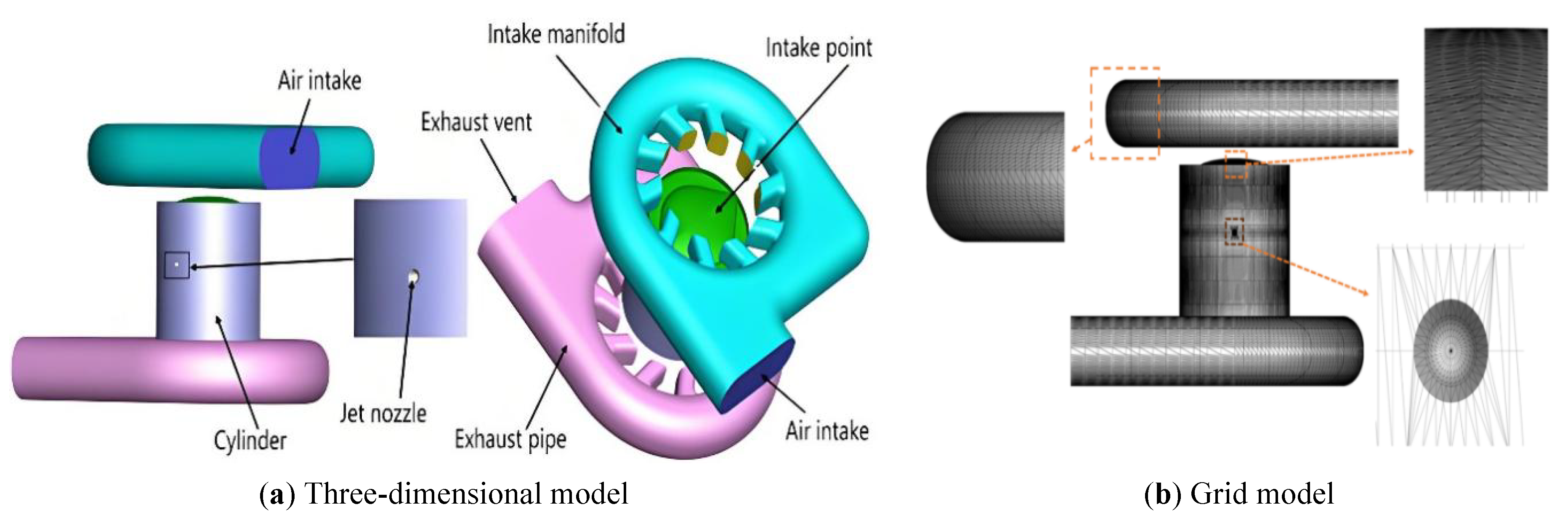
During simulation calculations, the temperature, pressure, fuel mass, and combustion products within the cylinder during combustion can be monitored and recorded. The key models employed in the simulation process are detailed in Table 2. Since we have previously validated the critical turbulence, spray, and combustion models [17], this paper concisely lists only the key model information employed. The experimental data align well with simulation results, confirming the reliability of this simulation model (encompassing both key models and simplified mechanisms).
Selection of primary models and mechanisms for opposed-piston two-stroke engines.
| Select Object | Specific Model |
|---|---|
| Turbulence model | RNG K-ε |
| Spray model | KH-RT |
| Combustion model | SAGE |
| Chemical Reaction Mechanism | 32 components, 213-step reaction |
| Fuel | Diesel |
3. Operating Condition Design
The engine speed exerts a significant influence on the operational performance of diesel engines. Moderately increasing the rotational speed enhances turbulence intensity within the cylinder, thereby improving the homogeneity of the fuel-air mixture and promoting stability during the initial combustion phase. This approach elevates combustion efficiency and power output. Moreover, precise control of injection timing plays a decisive role in the engine’s combustion process and power output. Designing this parameter facilitates optimal blending of fuel and air under ideal conditions, substantially enhancing combustion efficiency and power performance. Therefore, to analyze the influence of engine speed and fuel injection timing on engine performance, this paper constructed a model of a UAV opposed-piston engine. With the injection timing set at −20 °CA and the injection duration set at 15 °CA, five typical rotational speed conditions (1000, 1500, 2000, 2500 and 3000 r/min) were examined. When investigating the impact of injection timing, the engine speed was fixed at 2000 r/min with an injection duration of 15 °CA. Five injection timing schemes (−15, −20, −25, −30 and −35 °CA) were designed. The specific schemes are detailed in Table 3.
Operating conditions design for different rotational speeds and injection timing.
| Scheme Name | Injection Timing | Spray Duration | Rotational Speed |
|---|---|---|---|
| Case1 | −20 °CA | 15 °CA | 1000 r/min |
| Case2 | 1500 r/min | ||
| Case3 | 2000 r/min | ||
| Case4 | 2500 r/min | ||
| Case5 | 3000 r/min | ||
| Case6 | −15 °CA | 2000 r/min | |
| Case7 | −20 °CA | ||
| Case8 | −25 °CA | ||
| Case9 | −30 °CA | ||
| Case10 | −35 °CA |
4. Results and Discussion
4.1. Influence of Rotational Speed on Engine Performance
4.1.1. Gas Flow Process and Turbulent Kinetic Energy in-Cylinder
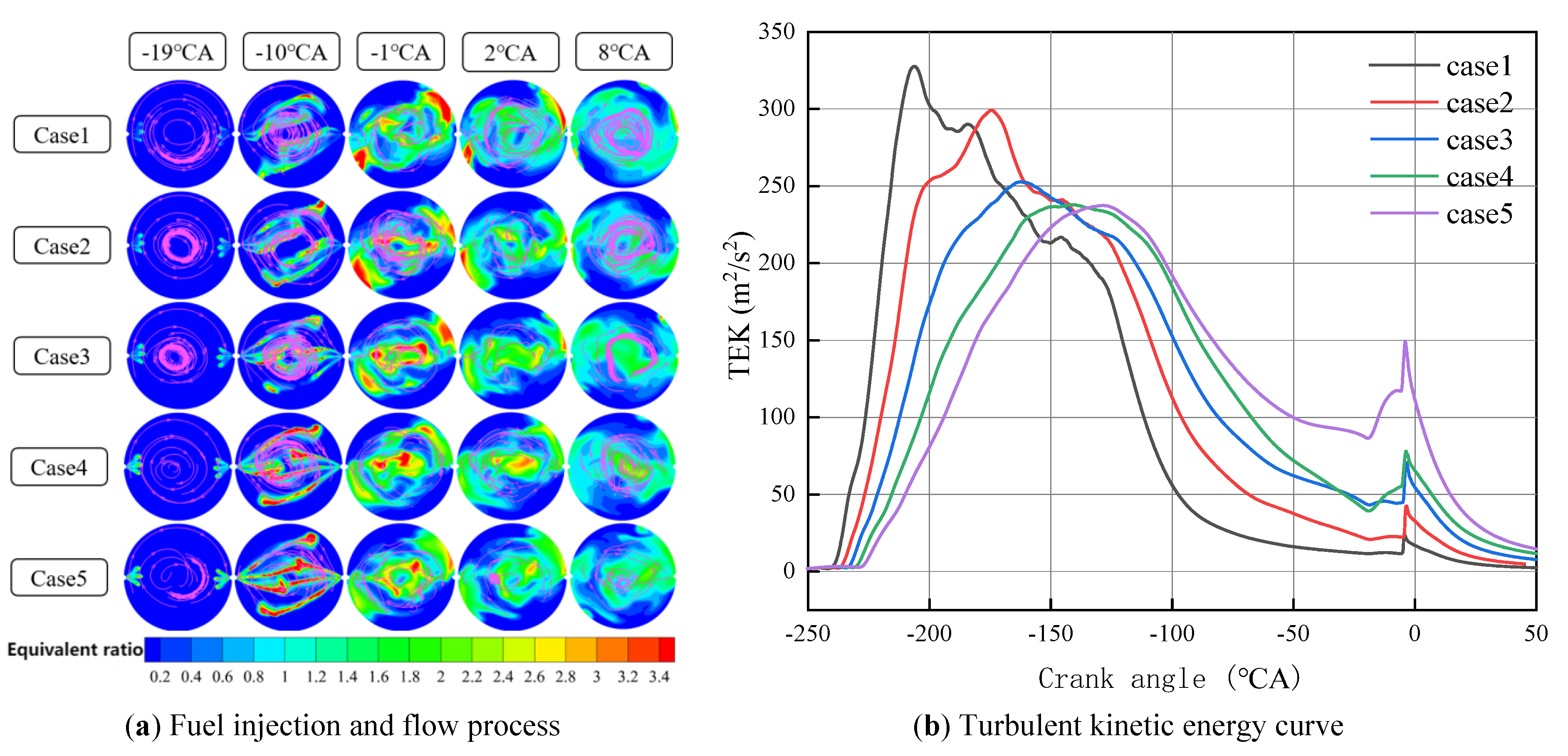
Figure 2a illustrates the flow behavior of fuel injected into the cylinder under different rotational speed conditions. Figure 2b shows the variation curve of in-cylinder turbulent kinetic energy under different rotational speed conditions. During low-speed, high-load engine operation, the relatively low rotational speed prolongs combustion duration, increasing knock susceptibility. Ignition delay phenomena emerge below 2000 r/min. This delay improves as rotational speed increases to 2000 r/min and above. With rising rotational speed, the peak maximum turbulent kinetic energy gradually diminishes across all operating conditions.
4.1.2. Combustion Process and Power Performance
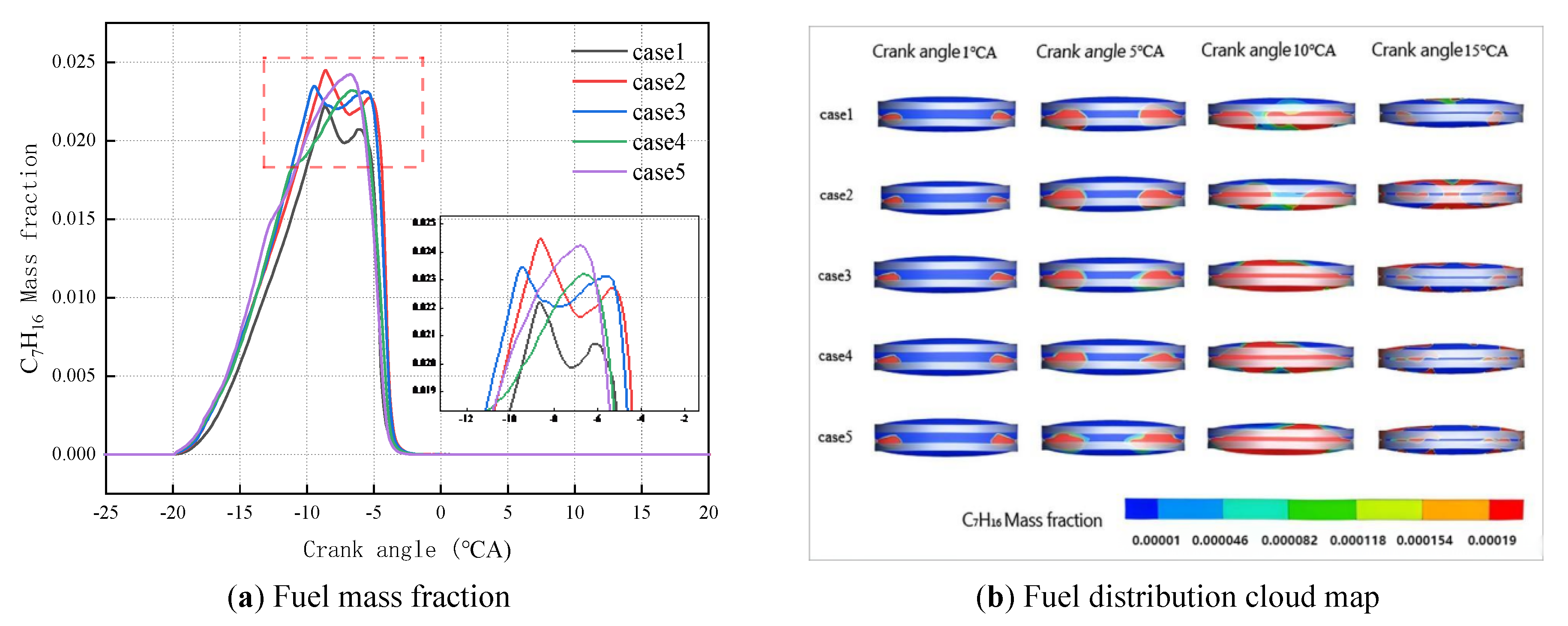
Figure 3 illustrates mass fraction and distribution contour in-cylinder under different rotational speed conditions, which primarily serves to analyze variations in unburned fuel within the cylinder. The figure demonstrates that in cases 1, 2 and 3, the fuel mass fraction initially increases rapidly after the crankshaft angle reaches −20 °CA, subsequently decreasing before gradually rising again when the crankshaft angle approaches approximately −7 °CA. This occurs because, under all three operating conditions, the injector commences operation at −20 °CA and delivers fuel into the cylinder. The entire injection process spans 15 °CA, during which the injector continuously introduces substantial quantities of fuel into the cylinder. The fuel mixes with air and undergoes compression, and once the crankshaft angle exceeds −10 °CA, the compressed mixture reaches its ignition temperature and self-ignites. The fuel within the cylinder undergoes vigorous combustion, consuming at a relatively high rate and gradually diminishing in concentration. However, not all injected fuel is fully consumed at this stage. As combustion progresses, the burning rate stabilizes, yet the injector continues to operate. Consequently, the rate of fuel consumption becomes lower than the rate of injection increase, leading to a renewed rise in the mass fraction of fuel. For case 4 and case 5 operating conditions, the fuel content increases continuously from the start of injection, indicating combustion has not yet commenced within the cylinder. When the crankshaft angle reaches approximately −5 °CA, fuel injection ceases and the fuel content peaks. Combustion continues thereafter, ultimately consuming all fuel, causing its mass fraction to rapidly decrease to zero. Under identical injection timing conditions, the fuel content in case 3 exhibits the swiftest response, indicating the earliest initiation of combustion.
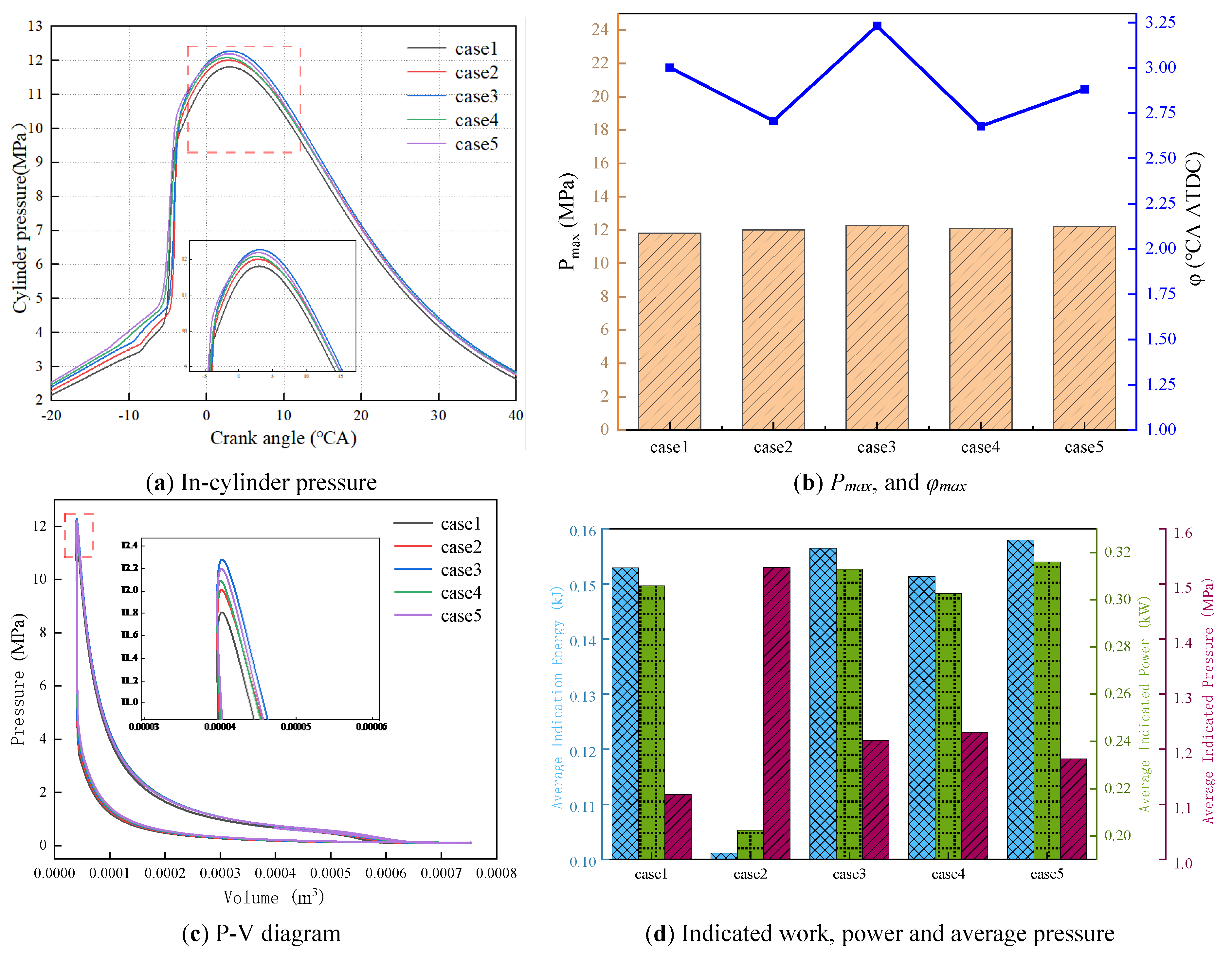
To sufficiently characterize combustion behavior across different rotational speed conditions, basic combustion parameters such as cylinder pressure, Pmax, and φmax are employed to describe the engine’s combustion characteristics, as illustrated in Figure 4a,b. As the rotational speed increases from 1000 to 2000 (r/min), the cylinder pressure exhibits an upward trend and reaches a peak at 2000 r/min; however, the cylinder pressure exhibits a decreasing trend when the rotational speed increases from 2000 to 3000 (r/min). Under all five operating conditions, the cylinder pressure peaked at approximately 3 °CA, indicating that the piston had reached top dead center at this timing. The cylinder pressure ceased to rise, signifying the end of the compression stroke and the imminent commencement of the power stroke. Besides, to investigate the engine combustion performance and power characteristics, the parameters, such as indicated work, power and average pressure, are analyzed, as shown in Figure 4c. Indicated work refers to the useful work transferred to the piston by the working medium during one complete engine cycle. The indicated power denotes the indicated work performed by the engine per unit time. The indicated average pressure represents the cycle work performed per unit cylinder working volume [18]. When evaluating engine performance, pressure-volume (P-V) diagrams are commonly plotted, with the net area enclosed by the curve representing the engine’s indicated work [19]. The figure indicates that the indicated work is highest under the operating condition of case 3. As rotational speed increases from 1000 to 2000 (r/min), indicated work progressively rises; conversely, it gradually decreases when speed escalates from 2000 to 3000 (r/min). In Figure 4d, the engine exhibits a high value average indicated work and indicated power for case 3 and case 5, demonstrating their superior dynamic performance. Although the average indicated pressure in case 3 is slightly higher than that of case 5, the difference is small, reflecting similar cylinder working volume utilization rates between the two cases.
4.1.3. Combustion Temperature and Exhaust Emissions Analysis
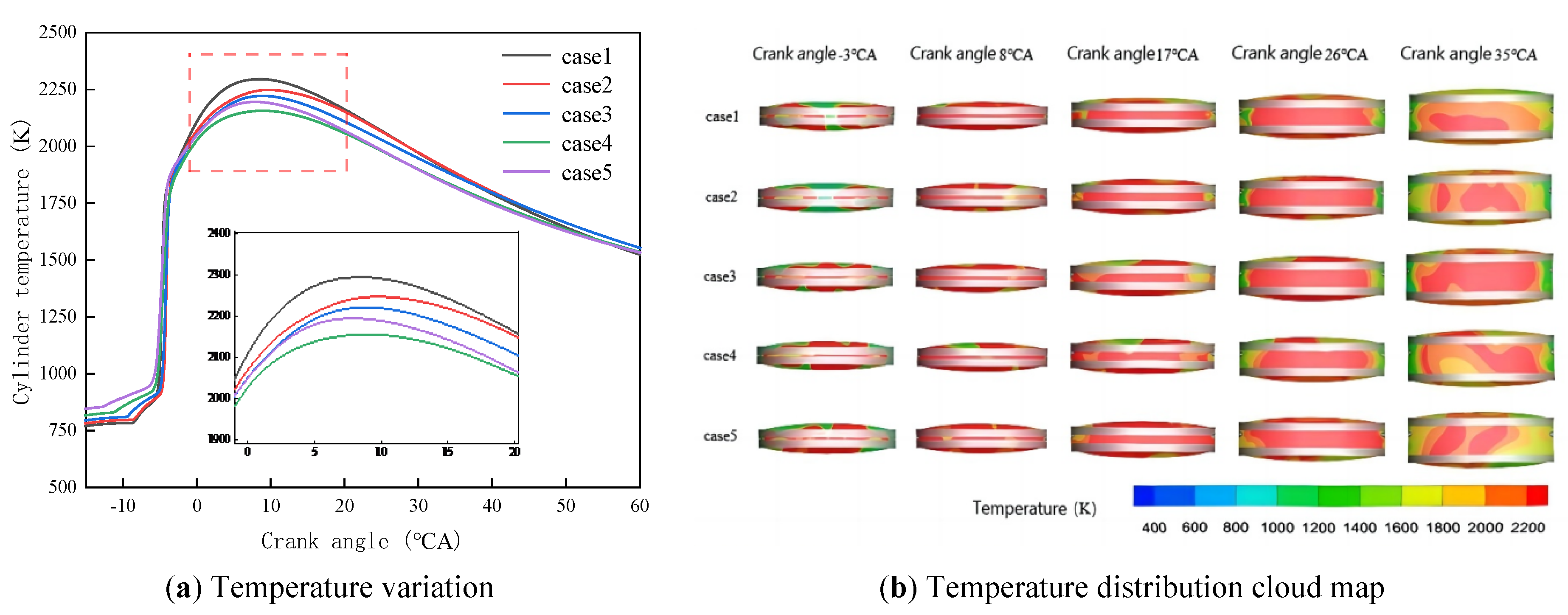
Figure 5 illustrates the temperature variation curves and their distribution cloud map under different rotational speed conditions. Analysis of the curves reveals that temperatures undergo rapid changes after the crankshaft angle reaches −5 °CA. This indicates that the mixed fuel, following compression, initiates combustion at this point, releasing substantial combustion heat and causing a swift rise in cylinder temperature. At 10 °CA, the temperature reaches its peak before commencing a descent, signifying the conclusion of the combustion process within the cylinder. Based on these five operating conditions and the overall trend of the temperature curve, it can be established that temperature changes slightly with an increase in rotational speed.
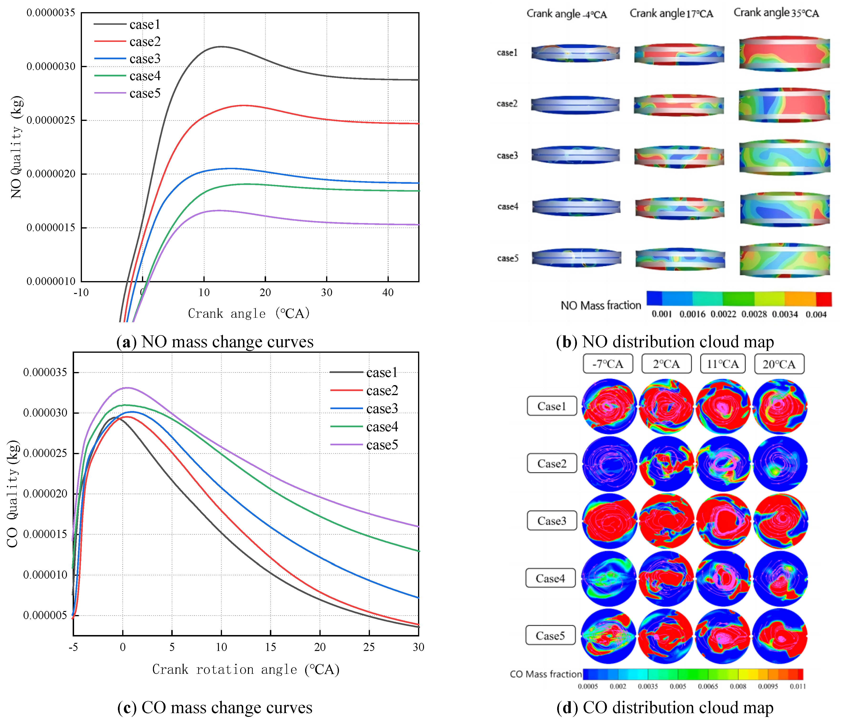
The combustion products of nitrogen oxides (NOx) and carbon monoxide (CO) are analyzed. NOx is formed predominantly through the oxidation of atmospheric oxygen and nitrogen at temperatures exceeding 1800 K, and its production increases with rising temperatures and higher oxygen concentrations [20]. Besides, in an ideal combustion process, fuel should undergo complete combustion, yielding primarily carbon dioxide and water; incomplete combustion, however, generates significant quantities of CO. Incomplete combustion not only increases CO emissions but also elevates fuel consumption. Figure 6a,b illustrate the NO mass variation curve and distribution cloud map under different rotational speed conditions. Analysis of the curve indicates that NO concentration peaks when the crankshaft angle reaches 10 °CA. Corroborating the temperature curve in Figure 5a, an increase in temperature leads to a corresponding rise in NO mass fraction. Figure 6c,d depict the CO mass variation curve and its distribution cloud map. In Figure 6c, the mass of CO in the exhaust emissions increases with rising engine speed. This occurs because, although fuel combustion becomes more complete at excessively high engine speeds, the reduced combustion duration may result in partial fuel being expelled from the combustion chamber before achieving full combustion, thereby increasing CO emissions. The mass of CO in cases 1, 2, and 3 shows no significant variation, whereas cases 4 and 5 exhibit a marked increase in CO mass.
4.2. Influence of Injection Timing on Engine Power Performance
4.2.1. Flow and Combustion Process in-Cylinder analysis
Figure 7 shows the fuel mass fraction and fuel distribution under different injection timing conditions. According to Figure 7, an earlier injection timing may enhance the turbulent motion in-cylinder through the action of the fuel jet. However, following the conclusion of injection, the mixing of fuel-air will further weaken as the crankshaft angle increases. At the fuel injection timing, the fuel entering the cylinder results in a rapid overall increase in the fuel mass fraction, and upon injection completion, the fuel mass reaches its peak value. With increased temperature and pressure, fuel is rapidly consumed during the combustion process, which means that all curves show that the later the jetting occurs, the later the peak time is.
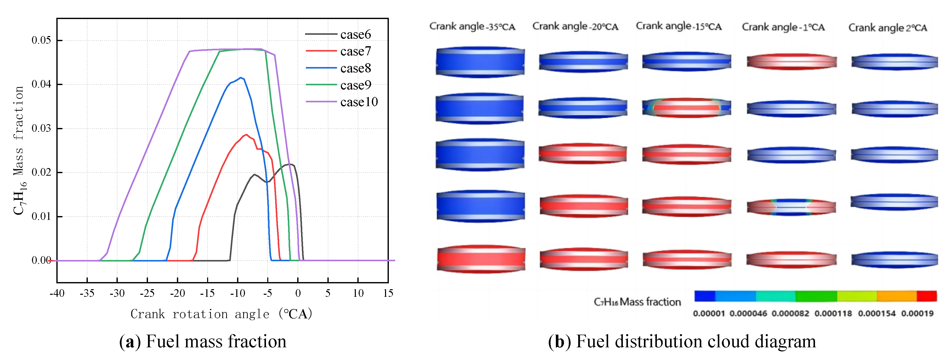
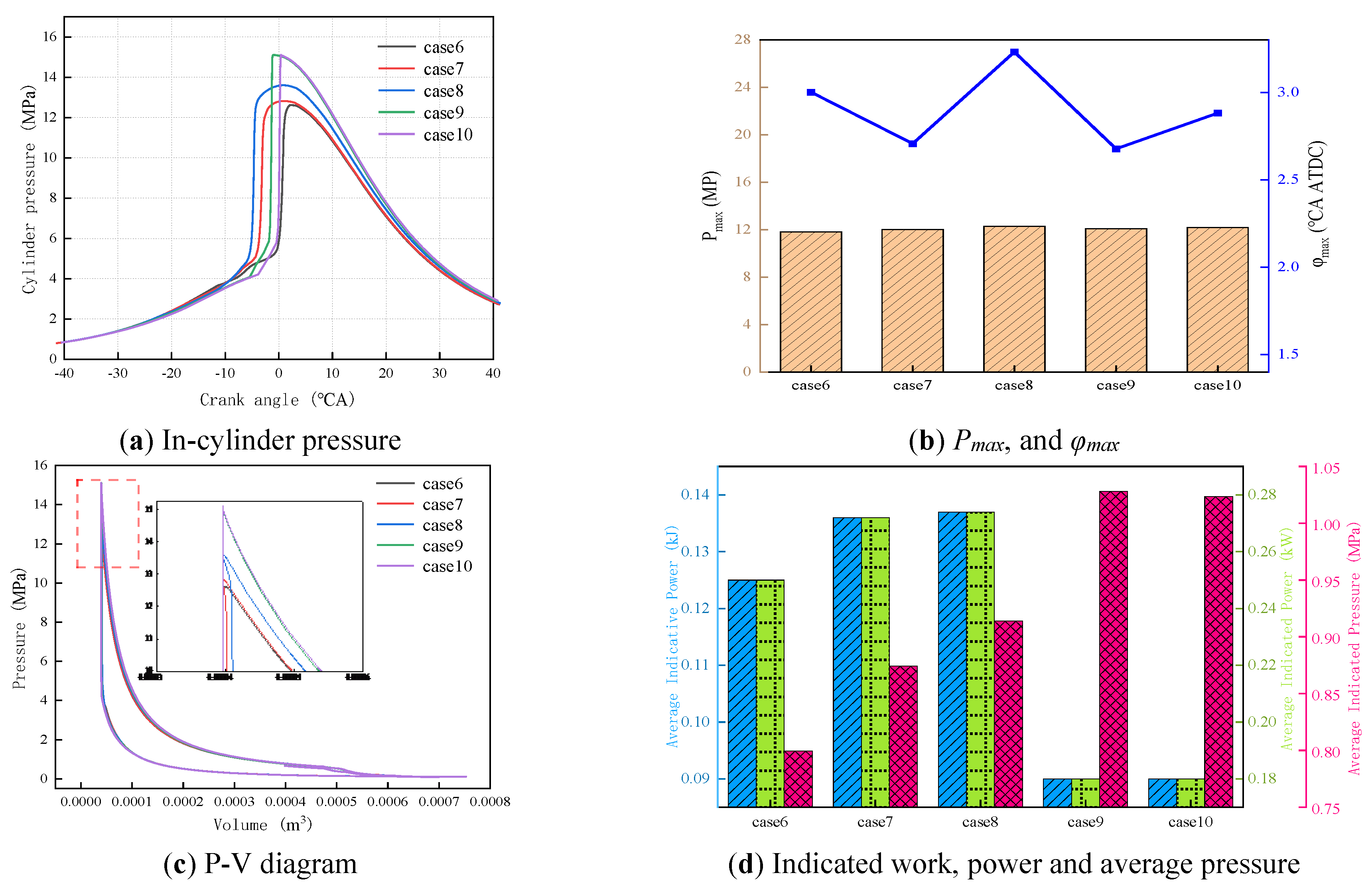
Figure 8a,b show the engine combustion and power parameters under different injection timing conditions. During the initial injection phase, the cylinder pressure curves’ total change rule for all five scenarios largely coincide. However, the rate of pressure rise in the cases of 9 and 10 are deviations from the cases of 6, 7, and 8. The curves in the figure indicate that earlier injection timing results in a higher peak cylinder pressure after injection completion. For all operating conditions, the peak cylinder pressure occurs around ATDC 3 °CA. This indicates that advancing the injection timing prolongs the mixing duration between fuel and air, thereby increasing the rate of mixture formation and the overall heat release rate during combustion. Analysis of the heat release rate diagram reveals that earlier injection timing results in both an earlier onset of heat release and a higher release rate. This demonstrates that altering injection timing influences the degree of fuel combustion, thereby affecting heat release. Among them, the earliest heat release can lead to a greater heat release rate, and case 8 exhibits the highest heat release. The engine power parameters are shown in Figure 8c,d. In general, a trend where engine indicated power increased with earlier injection timing, and case 8 exhibited the highest indicated power. For the cases of 6, 7 and 8, the engine indicated power, pressure, and all exhibit a gradual increase. This indicates that as the injection timing advances, engine power performance increases.
4.2.2. Combustion Temperature and Emissions Analysis
Figure 9 illustrates temperature curves and the distribution cloud map under different injection timing conditions. Analysis of the curve trends in Figure 9a reveals that temperatures undergo a rapid rise beyond a crankshaft angle of approximately −5 °CA. The temperature peaks around a crankshaft angle of 8 °CA, after which it begins to decline, indicating the conclusion of the combustion process in the cylinder. Based on these five operating conditions and the overall trend of the temperature curve, it can be established that an advancement in injection timing is accompanied by a corresponding rise in cylinder temperature.
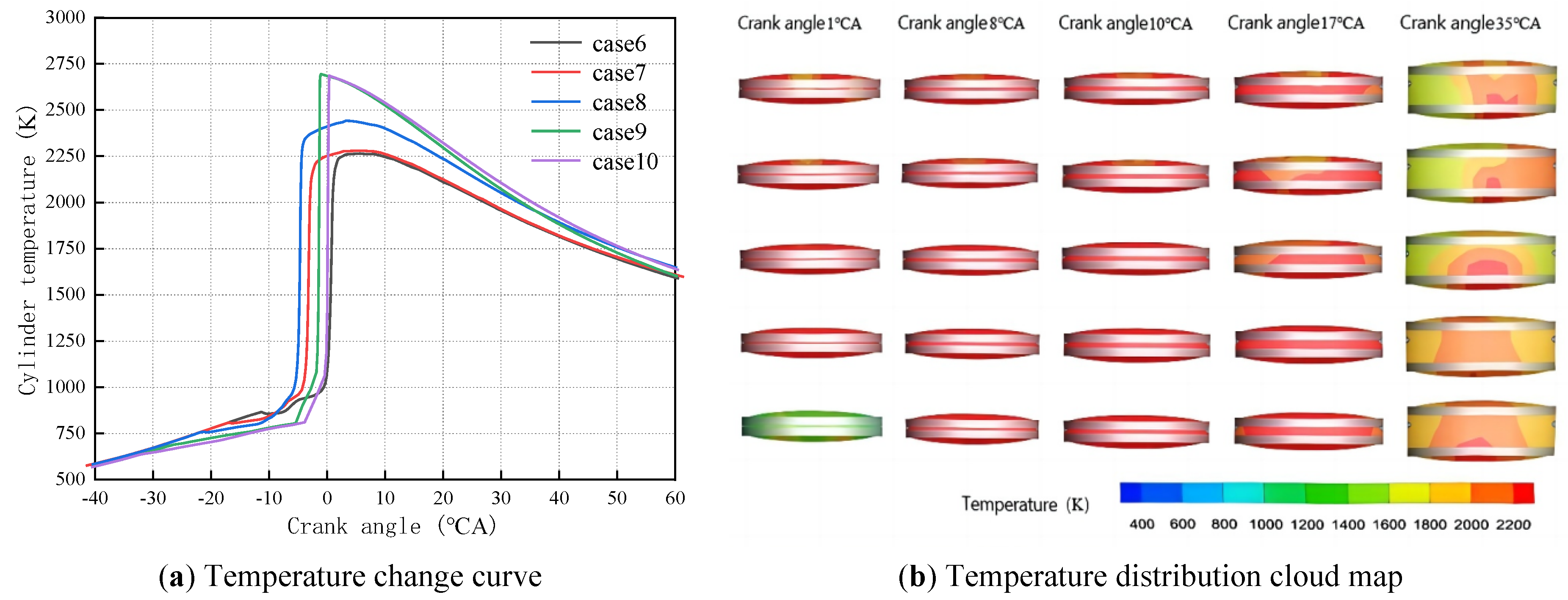
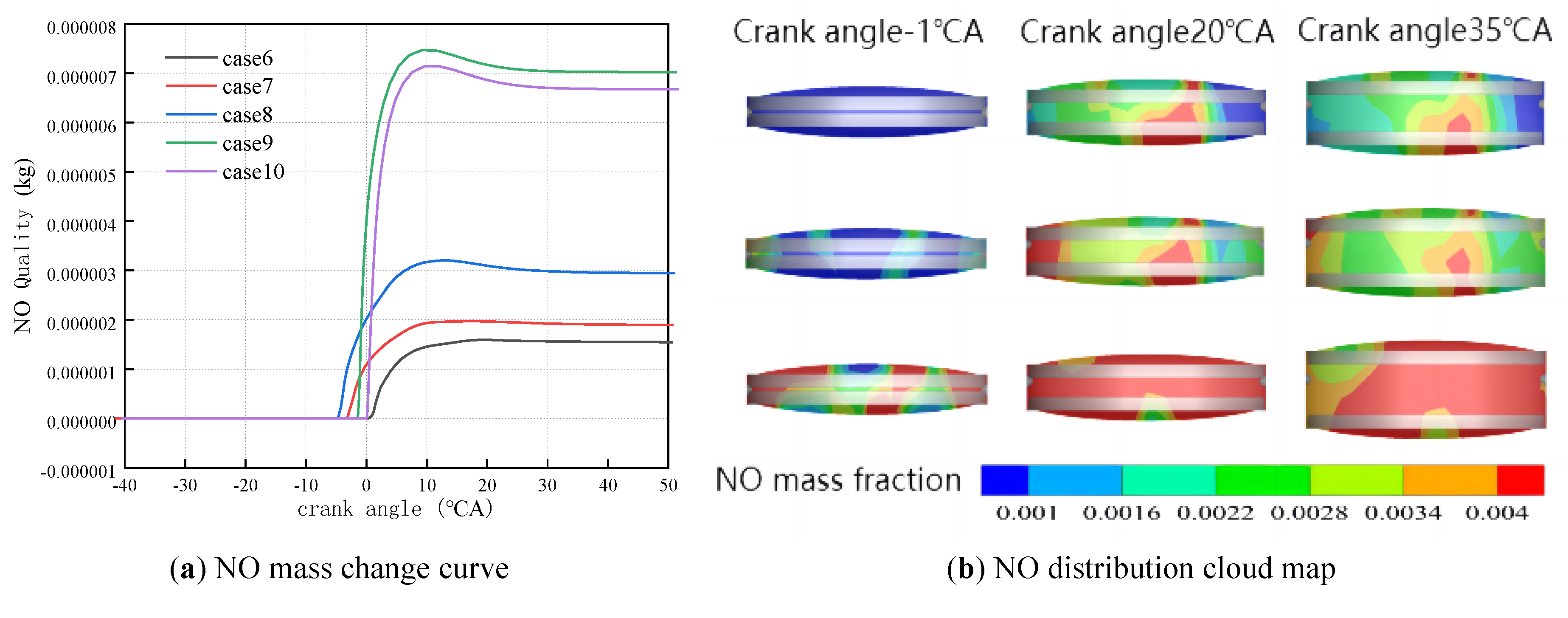
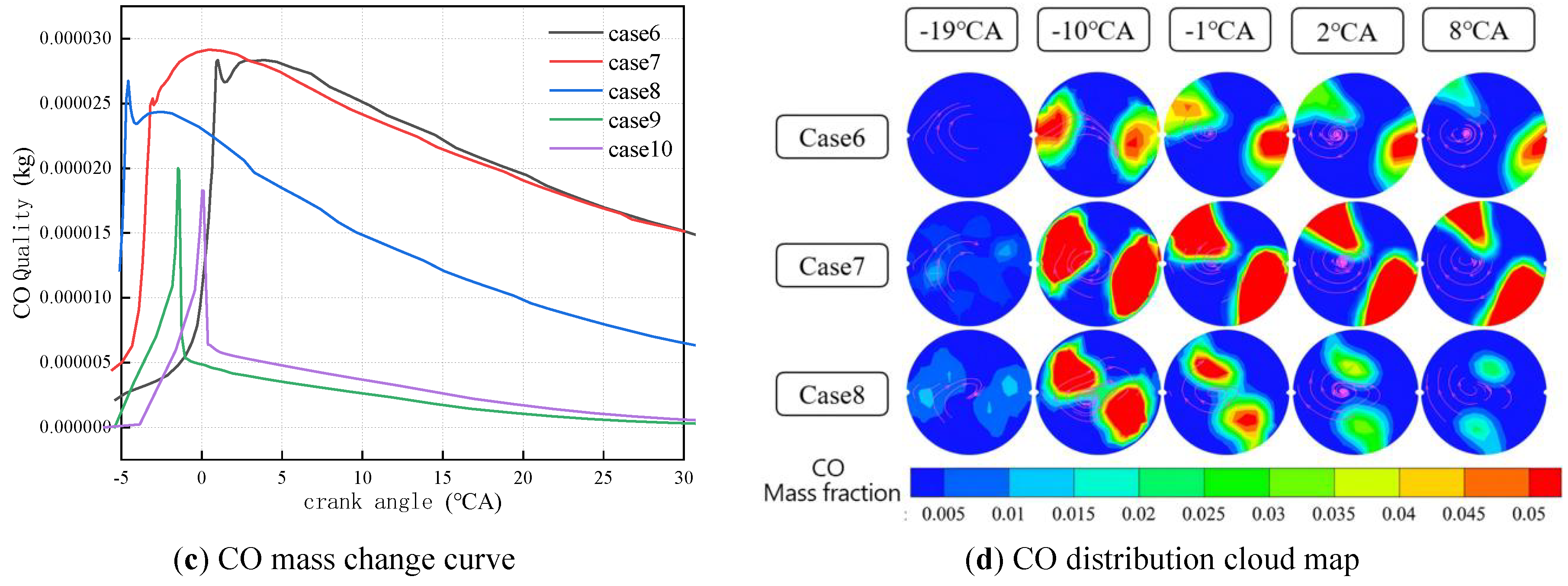
Figure 10 depicts the NO and CO mass variation curves and their distribution cloud map under different injection timing conditions. In Figure 10a, for cases of 6, 7 and 8, earlier injection timing correlates with higher NO content in emissions, with case 8 exhibiting the highest NO concentration. This occurs because advancing injection timing increases cylinder temperature, promoting more complete fuel combustion and thereby reducing emissions. However, this may also lead to increased NOx emissions due to elevated temperatures. Analysis of Figure 10c,d reveals that the cylinder CO mass gradually decreases as injection timing advances. This occurs because earlier injection allows fuel to enter the combustion chamber sooner, thereby increasing the mixing time between fuel and air and improving the homogeneity of the mixture. A more uniform mixture distribution enhances combustion efficiency, reduces the likelihood of incomplete combustion, and consequently lowers CO formation. Concurrently, advancing injection timing may lead to earlier combustion phase initiation. This signifies the combustion process commencing at an earlier crankshaft angle, potentially stabilizing the combustion process and reducing incomplete combustion. Advancing the combustion phase may elevate cylinder temperatures. Higher temperatures accelerate combustion reactions, promoting CO oxidation and consequently reducing CO emissions. An earlier injection timing allows fuel a greater time and space to atomize upon entering the combustion chamber, forming finer fuel droplets. This facilitates fuel-air mixing, enhances combustion efficiency and diminishes CO formation.
5. Conclusions
This paper focuses on investigating the combustion characteristics and power performance of an opposed-piston two-stroke UAV engine. Key engine parameters were determined based on UAV power requirements, and an engine simulation model was constructed and validated through experimental data to ensure the reliability of simulation results. Five typical rotational speed conditions (1000 to 3000 r/min) and injection timing conditions (−15 to −35 °CA) were designed. The effects of rotational speed and injection timing on engine combustion characteristics and power performance were investigated. Finally, by comparing flow and combustion data, the variation patterns were summarized and optimal operating conditions determined, and the conclusions include:
(1) Overall, increasing engine speed enhances in-cylinder flow and combustion performance, while delaying injection timing also improves combustion efficiency. However, engine speed and injection timing must be appropriately designed to meet the requirements for smooth engine operation.
(2) Considering the combined effects of rotational speed and injection timing on combustion, power, and emission performance, the optimal operating condition for the opposed-piston two-stroke engine used in unmanned aerial vehicles is determined to be 2000 r/min rotational speed with injection timing set to −20 °CA.
(3) Under the optimal operating conditions, ignition delay phenomena are mitigated, cylinder pressure remains moderate and stable, total heat release, indicated work and indicated power achieve a reasonable optimal level, and NO and CO emissions are maintained within acceptable limits. An optimal balance between combustion stability, power performance and emissions is achieved, which can meet the UAV’s operational demands for lightweight, high-efficiency engines.
Author Contributions
L.W.: writing—original draft preparation; Y.L.: data curation, investigation; X.K.: visualization; J.Y. (Jiajun Yan): software, validation; J.Y. (Jinhao Yan): formal analysis; Z.Z.: software; W.C.: writing—reviewing and editing, supervision. All authors have read and agreed to the published version of the manuscript.
Funding
This work was funded by the projects of the Guangxi Science and Technology Major Program (GuikeAA24206057), the Scientific Research Fund of Hunan Provincial Education Department (24B0156), and the China Postdoctoral Science Foundation (2023MD734160).
Institutional Review Board Statement
Not applicable.
Informed Consent Statement
Not applicable.
Data Availability Statement
The data presented in this study are available on request from the corresponding authors.
Conflicts of Interest
Author Yan Li was employed by the company of Hunan Zhongchen Equipment Co., Ltd. and author Xiangen Ke was employed by the company of Sany Automobile Co., Ltd. The remaining authors declare that the research was conducted in the absence of any commercial or financial relationships that could be construed as a potential conflict of interest.
Use of AI and AI-Assisted Technologies
No AI tools were utilized for this paper.
References
- 1.
Yang, W.; Li, X.R.; Kang, Y.N.; Zuo, H.; Liu, F.S. Evaluating the scavenging process by the scavenging curve of an opposed-piston, two-stroke (OP2S) diesel engine. Appl. Therm. Eng. 2019, 147, 336–346.
- 2.
Ma, F.; Yang, W.; Wang, Y.; Xu, J.; Li, Y. Experimental research on scavenging process of opposed-piston two-stroke gasoline engine based on tracer gas method. Int. J. Engine Res. 2022, 23, 1969–1980.
- 3.
Gainey, B.; Bhatt, A.; O’Donnell, P.; Prucka, R.; Filipi, Z.; Redon, F.; Lawler, B. Experimental Study of the Impact of Scavenging Efficiency on Diesel Combustion in an Opposed-Piston Two-Stroke Engine. Int. J. Engine Res. 2023, 24, 2921–2935.
- 4.
Tekin, O.; Barzegar, R.; Söylemez, S.M. Numerical Design of a New LPG-Fueled Opposed Piston Engine. Appl. Therm. Eng. 2025, 280, 128449.
- 5.
Serrano, J.R.; Arnau, F.J.; Bares, P.; Gomez-Vilanova, A.; Garrido-Requena, J.; Luna-Blanca, M.J.; Contreras-Anguita, F.J. Analysis of a Novel Concept of 2-Stroke Rod-Less Opposed Pistons Engine (2S-ROPE): Testing, Modelling, and Forward Potential. Appl. Energy 2021, 282, 116135.
- 6.
Furze, S.F.; Barraclough, S.; Liu, D.; Melendi-Espina, S. Model Based Mapping of a Novel Prototype Spark Ignition Opposed-Piston Engine. Energy Convers. Manag. 2024, 309, 118434.
- 7.
Animashaun, M.; Qiu, S.; Li, H. A Theoretical Framework for the Analysis of an Opposed Piston Linear Engine Design. Results Eng. 2024, 22, 102086.
- 8.
Wang, W.; Liang, Y.; Zuo, Z.; Jia, B.; Wang, W. Study on the Influence Principle and Application Law of Intake Wall Thickness on Uniflow Scavenging Opposed-Piston Engine. Energy 2024, 291, 130271.
- 9.
Pei, T.; Chen, F.; Qiu, S.; Wu, D.; Gao, W.; Xu, Z.; Zhang, C. Research on the Intake Port of a Uniflow Scavenging GDI Opposed-Piston Two-Stroke Engine. Energies 2022, 15, 2148.
- 10.
Li, S.; Qin, J.; Pei, Y.; Du, T.; Liang, Y.; Wu, M. Investigation into Scavenging and Combustion Performance with Unique Intake System on Opposed-Piston Two-Stroke Engines. Appl. Therm. Eng. 2025, 274, 126706.
- 11.
Zhu, Z.; Li, Y.; Xie, Y.; Sun, C.; Yang, Z. Combustion System Optimization and Knock Characteristics of a Two-Stroke Rod-Less Opposed-Piston Engine. Int. J. Engine Res. 2025, 26, 1058–1069.
- 12.
Ma, F.; Yang, W.; Xu, R.; Liu, X. Combustion Cycle-to-Cycle Variations of Opposed-Piston Two-Stroke Gasoline Direct Injection Engine. Int. J. Engine Res. 2024, 25, 717–726.
- 13.
Zhang, L.; Su, T.; Zhang, Y.; Ma, F.; Yin, J.; Feng, Y. Numerical Investigation of the Effects of Split Injection Strategies on Combustion and Emission in an Opposed-Piston, Opposed-Cylinder (OPOC) Two-Stroke Diesel Engine. Energies 2017, 10, 684.
- 14.
Yang, W.; Li, X.R.; Zhao, W.H.; Kang, Y.N.; Liu, F.S. Effect of Layered-Port VVT on Performance of Opposed-Piston Two-Stroke Diesel Engine. J. Energy Eng. 2019, 145, 04019027.
- 15.
Zhong, L.; Xin, Q.; Liu, R.; Raihanul, I.; Saiful, I.M.; Chen, Y. Visual Multi-Objective Optimization of the Performance of a Two-Stroke Aviation Piston Engine with the Predictive Combustion Model at Different Altitude Based on 3D Scavenging Computation. Energy 2025, 335, 138364.
- 16.
Lu, D.L.; Zheng, J.; Hu, C.B.; Bian, S.C. Research on the Development Status of General Aviation Piston Engines. Intern. Combust. Engines Parts 2019, 8, 64–66. https://doi.org/10.19475/j.cnki.issn1674-957x.2019.08.029. (In Chinese)
- 17.
Chen, W.; Yang, X.; Zuo, Q.; Wang, H.; Ning, D.; Kou, C.; Zhang, Y.; Zhu, G. Combustion Characteristics and Performance Analysis of a Heavy-Fuel Rotary Engine by Designing Fuel Injection Position. Appl. Therm. Eng. 2024, 247, 123021.
- 18.
Feng, K. Fuel Saving Potential Study of Atkinson Cycle Applied on an Automotive Gasoline Engine. Master Thesis, Hunan University, Changsha, China, 2013. (In Chinese)
- 19.
Jia, Q.Q. Study on the Fuel Injection and Combustion Property of Light-Weight, Two-Stroke, GDI Aeroengine. Master Thesis, Beijing Jiaotong University, Beijing, China, 2014. (In Chinese)
- 20.
Yang, Y.K. The Effect of Ignition Advance Angle on the Combustion and Emission Characteristics of A hydrogen Engine. Master Thesis, North China University of Water Resources and Electric Power, Zhengzhou, China, 2017. (In Chinese)

This work is licensed under a Creative Commons Attribution 4.0 International License.

 Suite 4002 Level 4, 447 Collins Street, Melbourne, Victoria 3000, Australia
 General Inquiries: info@sciltp.com