Diesel spray characteristics play a crucial role in determining combustion quality, engine performance, and exhaust gas emissions. Previous studies have primarily focused on spray behavior and its influence on combustion using production-type multi-hole diesel injectors. However, the potential for improving engine performance and emission characteristics through modifications to injector internal components has not yet been sufficiently explored. This study experimentally investigates the effects of injector internal component modification on diesel spray characteristics, with the aim of clarifying the relationship between internal injector configuration and spray behavior. Macroscopic high-speed imaging was employed to characterize the temporal evolution of the injected spray, while injection-rate measurements were conducted to evaluate changes in fuel delivery behavior resulting from the internal modification. The analysis focuses on the correlation between injector internal modification and the resulting spray characteristics. The results demonstrate that modification of injector internal components significantly influences diesel spray behavior, particularly during the early stage of injection, through changes in injection-rate development and spray formation processes.
- Open Access
- Article
Experimental Investigation of Diesel Spray Behavior Influenced by Injector Internal Component Modification
- Raditya Hendra Pratama 1,*,
- Weidi Huang 2,
- Yusuke Senzai 3
Author Information
Received: 12 Mar 2026 | Revised: 22 Apr 2026 | Accepted: 11 May 2026 | Published: 12 Jun 2026
Abstract
Keywords
diesel spray | injector internal modification | injection rate | spray characteristics | high-speed visualization
1. Introduction
Stringent exhaust gas emission regulations worldwide have compelled engine manufacturers to continuously advance engine technologies to comply with increasingly strict standards. In diesel engines, emission reduction strategies mainly focus on two approaches: optimization of the combustion system and improvement of exhaust after-treatment systems. Among these strategies, enhancing fuel injection quality is of particular importance, as it directly promotes improved mixture formation and combustion efficiency, thereby contributing to higher thermal efficiency, which is a key indicator of engine performance. Fuel spray injection therefore plays a critical role in diesel engine operation, since the structure and spatial distribution of the injected spray strongly govern in-cylinder combustion behavior and emission formation. Achieving a well-distributed fuel spray within the combustion chamber is essential for stable and efficient combustion [1,2,3,4]. Nevertheless, previous studies have reported noticeable variations in diesel spray distribution among different injectors, suggesting inherent differences in spray characteristics even under similar operating conditions [5,6,7,8,9].
Diesel engines used in automotive applications are often tuned or modified from their original manufacturer settings to achieve improved performance tailored to specific driving conditions or user requirements. One common approach involves modifying the diesel fuel injection strategy to enhance engine performance. Such tuning can be achieved through remapping of fuel injection parameters via the engine control unit (ECU) and/or by physically modifying the internal components of the diesel fuel injector [10,11,12]. ECU remapping typically includes adjustments to injection timing [13,14,15,16,17,18,19], injection pressure [9,14,20,21,22], and injection strategies, such as multi-pulse or split injection [11,18,23,24]. In contrast, modifications to the injector internal components may involve adjusting shim thickness, altering nozzle geometry to achieve a desired nozzle hole configuration, or applying a combination of these approaches. In many practical cases, however, these modifications are performed without reference to manufacturer guidelines or systematic evaluation, relying instead on empirical experience or trial-and-error approaches. Consequently, there is a clear need for experimental investigations that examine injector internal part modifications based on scientific principles, enabling informed optimization of injection systems while minimizing potential adverse effects.
Modifications to injector internal components directly influence internal nozzle flow and, consequently, fuel spray characteristics. Numerous experimental studies have investigated the effects of internal nozzle flow on diesel spray behavior by varying key geometric parameters, including needle lift gap [25,26], number of nozzle holes [27,28], and nozzle angle [29]. These studies aimed to elucidate macroscopic spray characteristics such as spray penetration and cone angle. Their findings consistently highlight the critical role of injector internal geometry in governing spray formation. In particular, needle valve motion and needle lift strongly affect flow structures within the sac volume and nozzle holes. These flow structures can induce recirculation and turbulence, leading to cavitation phenomena [30,31,32], as well as helical flow patterns associated with string cavitation [33,34,35,36,37]. Such complex internal flow behaviors ultimately influence the characteristics of the emerging fuel spray. Internal nozzle flow and resulting spray characteristics have been visualized using optical diagnostic techniques with either visible-light illumination [31,33,38] or X-ray [38,39,40,41]. In addition, computational fluid dynamics (CFD) approaches, including Reynolds-Averaged Navier–Stokes (RANS) two-phase flow models combined with Euler–Lagrangian spray modeling, have been employed to analyze hole-to-hole variations and spray formation processes [22].
Recent studies have emphasized the critical role of injector internal flow dynamics and design optimization in governing fuel injection and spray behavior. For instance, 3D-CFD-based investigations on alternative fuels such as oxymethylene ether (OME) have shown that injector nozzle geometry, spray angle, and injection strategy significantly influence injection-rate characteristics, needle dynamics, and overall engine efficiency and emissions [42]. In parallel, research on low-carbon fuel systems has reported the nonlinear nature of pilot injection, proposing curvature-based optimization strategies to precisely control injection-rate profiles through injector structural parameters and hydraulic response [43]. Furthermore, detailed analyses of internal flow behavior have revealed that dynamic needle oscillation induces complex vortex structures within the sac and nozzle, which can suppress the mass flow rate and strongly affect injection-rate shaping, particularly during transient opening and closing phases [44]. Complementing these findings, multiphase flow and cavitation modeling studies of asymmetric injectors have shown that nozzle geometry and operating pressure critically influence cavitation intensity, flow stability, and spray uniformity, with direct implications for atomization and emissions [45]. Collectively, these studies underscore the intricate coupling between injector internal configuration, needle motion, cavitation, and injection-rate development, highlighting the importance of internal component design in controlling spray formation and its potential impact on combustion behavior.
Despite extensive studies on diesel spray characteristics and their influence on combustion, most previous research has primarily utilized production-type injectors without considering modifications to the internal injector structure. Injection characteristics have typically been varied through conventional parameters such as injection pressure and injection duration. Existing studies have mainly focused on external nozzle parameters or injection strategies, while investigations of internal flow have emphasized cavitation and turbulence effects on spray formation. However, the influence of modifying injector internal components that directly affect needle motion and injection dynamics has not been sufficiently clarified. In particular, variations in shim thickness, which alter the mechanical response of the injector and consequently the injection-rate development, remain largely unexplored in relation to macroscopic spray behavior. Therefore, a clear research gap exists in understanding how such internal mechanical modifications influence the transient injection process and early-stage spray characteristics. To address this gap, the present study experimentally investigates the effect of upper shim thickness variation on injection-rate behavior and diesel spray development using high-speed visualization and injection-rate measurements, while keeping other injector components unchanged. This approach enables the controlled isolation of the influence of upper-shim modification on injector response and spray formation, which has not been clearly demonstrated in previous studies. Furthermore, it provides a systematic evaluation of the relationship between injector internal modification and spray characteristics, offering new insights into the role of internal injector dynamics in diesel spray formation. It should be noted that the present study focuses on macroscopic spray characteristics, and microscopic features, such as droplet size distribution and vapor-phase behavior, are beyond the scope of this work.
The novelty of this study lies in three key aspects. First, the effect of injector internal mechanical modification is systematically isolated by varying only the upper shim thickness while maintaining all other injector components unchanged. Second, a coupled analysis combining high-speed spray visualization and injection-rate measurement is employed to directly correlate injection dynamics with spray development. Third, the study identifies a distinct transient injection behavior under thinner shim conditions, characterized by delayed injection onset, slower rate development, and shortened effective injection duration, which may resemble a pilot-like injection feature arising from mechanical modification.
2. Experimental Setup
2.1. Diesel Injector Part Modification
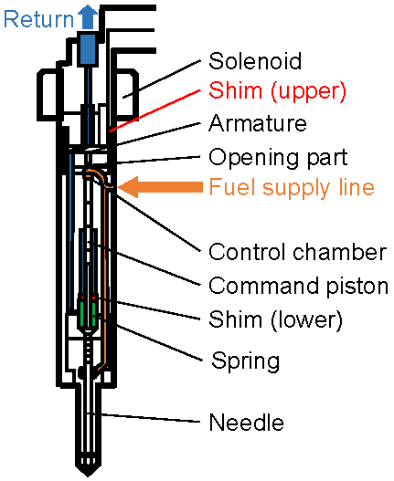
In this study, a commercially available common-rail solenoid-type diesel injector was employed as the baseline injector. Figure 1 shows the internal architecture of the injector unit. The injector was systematically modified by adjusting the thickness of its internal shim in order to investigate the effect of injector internal component modification on diesel spray characteristics. The injector contains two shims: an upper shim and a lower shim. The lower shim primarily governs the needle seat position and the needle lift gap within the sac volume, thereby directly affecting the nozzle internal geometry. Modifying the lower shim thickness would introduce simultaneous changes in multiple geometric parameters, making it difficult to isolate the influence of injector internal modification on spray behavior. For this reason, the lower shim was kept unchanged throughout the experiments. Instead, only the upper shim thickness was varied.
The upper shim plays a critical role in controlling the armature lift of the solenoid valve, which directly influences needle motion characteristics such as opening delay, lift profile, injection timing, injection rate, and injected fuel quantity. By modifying only the upper shim thickness, the needle motion was treated as the primary controlled variable, allowing a clearer interpretation of its influence on internal flow and subsequent spray characteristics. It should be noted that, even for injectors manufactured to identical specifications, factory-installed shim thicknesses may vary slightly to achieve consistent injection performance.
In this study, a single injector was used, and its upper shim thickness was systematically altered to eliminate injector-to-injector variability. The shim thickness variations were defined relative to the original factory-installed shim thickness, denoted as Δt, with four cases examined: Δt = 0, −10, −16, and −17 μm. These controlled modifications enabled a focused investigation of the relationship between injector internal component modification and diesel spray characteristics.
2.2. Backlight Imaging
Figure 2a illustrates the experimental setup employed for diesel spray imaging using high-speed backlight visualization. Diesel fuel was supplied to the injector through a common-rail injection system capable of pressurizing the fuel up to 300 MPa. The pressurized fuel was injected into a constant-volume spray chamber designed to provide optical access for spray visualization. The ambient environment inside the spray chamber was slightly pressurized using nitrogen gas to establish controlled and repeatable test conditions. An outlet valve located at the chamber exit was partially opened to allow the discharge of fuel droplets after injection, thereby preventing excessive fuel accumulation during repeated experiments. The experiments were conducted under atmospheric, non-evaporating conditions using nitrogen to isolate the influence of injector internal modification on spray behavior without the effects of evaporation and combustion process. Injection duration was adjustable up to 2.5 ms, enabling the simulation of both pilot and main injection events commonly employed in diesel engine operation. To maintain a comparable injected fuel quantity across different injection pressures, the injection duration was also adjusted accordingly. Therefore, comparisons at different injection pressures were performed under equal-injected-quantity conditions rather than fixed command duration. An eight-hole solenoid-type diesel injector with a designed nozzle hole diameter of 0.125 mm was used in this study. To isolate a single spray plume, a 1 mm thick spray blocker was installed at the injector tip, ensuring that only the intended spray was visualized and minimizing optical interference from adjacent sprays. Spray images were captured using a high-speed camera synchronized with the injection event through a delay generator, ensuring accurate temporal alignment between injector energizing and image acquisition. High-speed imaging was performed at a frame rate of 40,000 frames per second, allowing time-resolved observation of spray evolution from the start to the end of injection. Backlight illumination was provided by a metal halide lamp coupled with a light guide. The light source was positioned opposite the high-speed camera, in front of the chamber window, to generate a uniform backlight suitable for silhouette imaging of the spray. Under these conditions, spray development up to 50 mm downstream of the nozzle exit was captured with high spatial and temporal resolution. The spatial resolution of the imaging system was 48.7 μm/pixel, while the temporal resolution was 25 μs per frame. The recorded high-speed images were post-processed to analyze the spray injection process and to quantify macroscopic spray characteristics. In particular, spray tip penetration and spray angle, the two key parameters examined in this study, were evaluated.
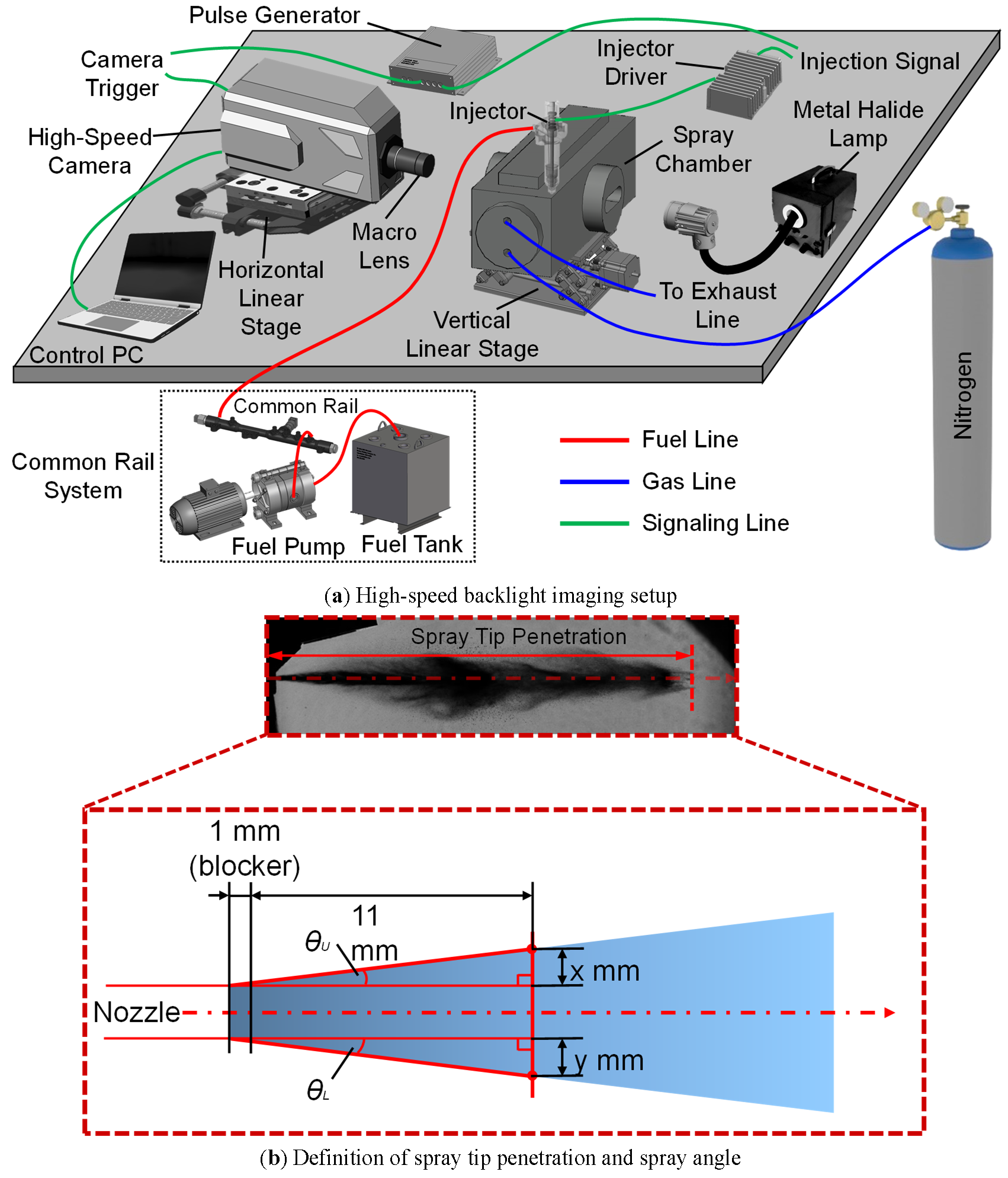
The spray images were processed using a grayscale thresholding method to extract the spray boundary. Each frame was converted into a binary image using a fixed intensity threshold to distinguish the liquid phase from the background illumination. The spray contour was then identified as the outer boundary of the binarized region. Spray tip penetration was defined as the axial distance from the nozzle exit to the furthest detected point of the spray boundary. The spray angle was determined by fitting straight lines along the upper and lower boundaries of the spray near the nozzle region, and calculating the corresponding angles relative to the nozzle axis, as defined in Equation (1). To ensure consistency, the same threshold value was applied across all test conditions. Under weak-signal conditions, particularly during the early stage of injection, the spray tip was defined only when a clearly continuous spray structure could be identified. The sensitivity of the results to threshold selection was checked and found not to significantly affect the overall trends. These procedures minimize uncertainty in boundary detection and ensure consistent comparison across different cases. Each condition was repeated five times, and the results showed good repeatability. Figure 2b presents a representative backlight image illustrating the measurement of spray tip penetration and spray angle. Detailed high-speed imaging parameters for backlight visualization are summarized in Table 1.
| Injector | ||||||||||||||||||||||||
|---|---|---|---|---|---|---|---|---|---|---|---|---|---|---|---|---|---|---|---|---|---|---|---|---|
| Injector | Solenoid, 8-hole | |||||||||||||||||||||||
| Fuel | Diesel | |||||||||||||||||||||||
| Injection Pressure | 65 MPa | 135 MPa | 160 MPa | 200 MPa | ||||||||||||||||||||
| Injection Duration | 2.220 ms | 1.390 ms | 1.240 ms | 1.070 ms | ||||||||||||||||||||
| Ambient | ||||||||||||||||||||||||
| Ambient Pressure | 0.1 MPa (N2) | |||||||||||||||||||||||
| Ambient Density | 1.25 kg/m3 | |||||||||||||||||||||||
| Visualization Setting | ||||||||||||||||||||||||
| Visualization Technique | High-Speed Backlight Imaging | |||||||||||||||||||||||
| Frame Rate | 40,000 fps | |||||||||||||||||||||||
| Temporal Resolution | 25 μs/frame | |||||||||||||||||||||||
| Shutter Speed | 0.25 μs | |||||||||||||||||||||||
| Captured Area | ≈49.9 × 24.9 mm | |||||||||||||||||||||||
| Image Resolution | 1024 × 512 pixel | |||||||||||||||||||||||
| Spatial Resolution | ≈ 46.8 μm/pixel | |||||||||||||||||||||||
| Number of Repetitions | 5 | |||||||||||||||||||||||
2.3. Injection Rate Measurement
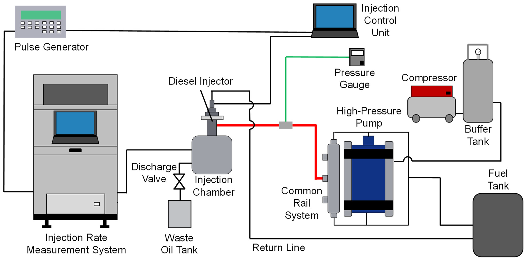
Figure 3 illustrates the experimental arrangement for injection rate measurement. Injection rate measurements were performed using a commercially available injection rate measurement system based on the Zeuch method. The system comprised injection rate analyzers equipped with a control personal computer and dedicated analysis software, a pulse generator, an injector driver, a common-rail fuel supply system, the test injector, an injection chamber, signal amplifiers, and a fuel discharge and recovery unit. The common-rail system was pressurized using an air-driven high-pressure pump, with compressed air supplied by an external compressor. This configuration enabled stable fuel pressurization up to 200 MPa. The test injector was actuated by an injector driver that received energizing signals from a pulse generator. The same pulse generator was also connected to the injection rate analyzers to ensure precise synchronization between injector actuation and data acquisition.
During injection, fuel was injected into a closed injection chamber equipped with high-frequency pressure transducers. The pressure signals generated inside the chamber were amplified and transmitted to the injection rate analyzers, where the instantaneous injection rate and total injected fuel quantity were calculated. After completion of each injection event and data acquisition, discharge and relief valves connected to the injection chamber were activated to release the injected fuel, ensuring repeatable initial conditions for subsequent measurements. Each experimental condition was repeated 5 times to ensure repeatability, and the results presented represent the averaged values.
The injection rate analyzer employs the Zeuch method, in which the instantaneous injection rate is derived from the rate of pressure increase in a chamber of known volume and fuel compressibility. This method allows accurate measurement of transient injection behavior, including needle opening and closing characteristics, and is suitable for multi-stage injection strategies such as pilot, main, and split injections commonly used in modern diesel engines. The measured injection rate profiles were subsequently used to evaluate the influence of injector internal part modification on injection dynamics and fuel delivery behavior.
3. Experiment Result
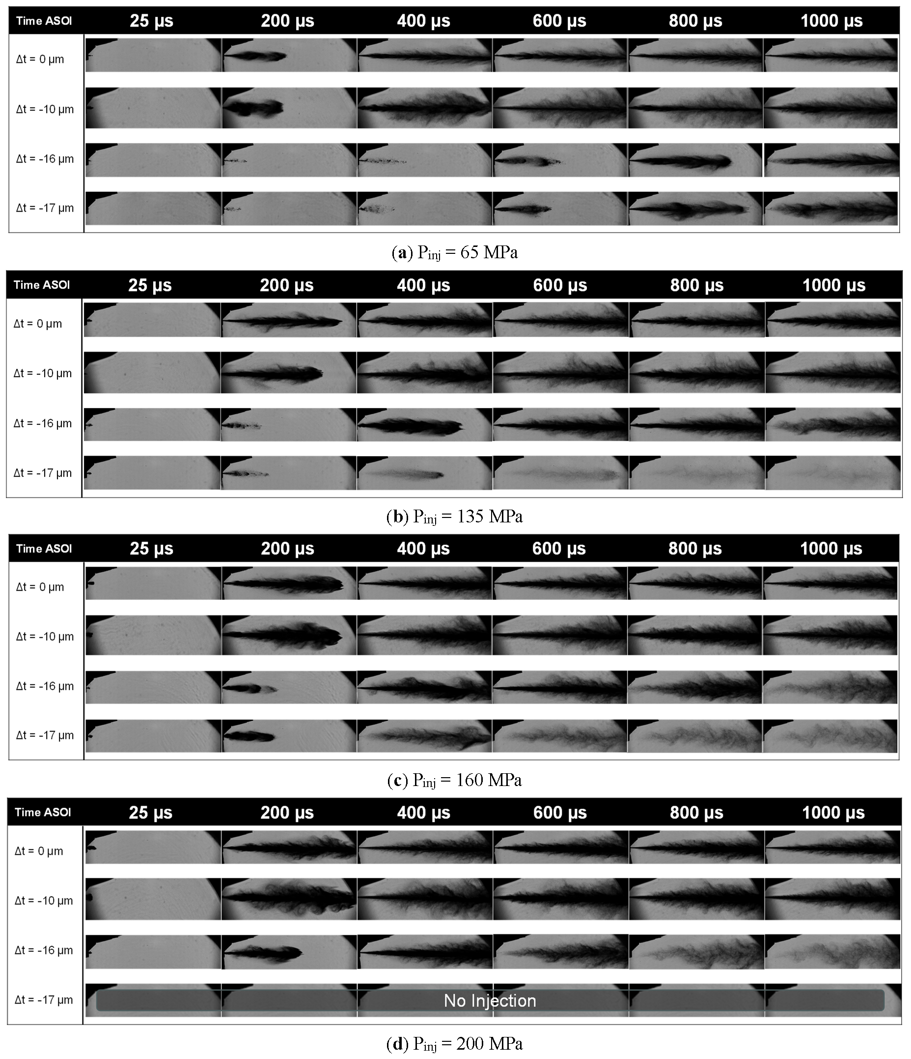
The spray development process was investigated using high-speed imaging to capture the temporal evolution of the injected diesel spray. It is well known that a finite delay exists between the time after start of injector energizing (ASOE) and the actual emergence of fuel from the nozzle orifice, commonly referred to as the time after start of injection (ASOI). This delay arises from the dynamic response of the injector’s internal components, including solenoid actuation and needle motion. Analysis of the high-speed images revealed that variations in upper shim thickness significantly affected this delay time. Changes in shim thickness altered the needle motion characteristics, resulting in different ASOE–ASOI delays among the tested cases. As a consequence, direct frame-by-frame comparison of spray images at identical times after energizing was not appropriate. To ensure consistent comparison of spray development, the observation time was therefore aligned based on the actual spray emergence. Specifically, the reference time was defined as 0 μs at the moment the spray exited the nozzle blocker hole, and spray images were analyzed from 25 μs after this reference time.
Figure 4 presents time-resolved spray images obtained under various injection pressures and upper shim thickness conditions. The results clearly show that injectors with thinner upper shims exhibit slower spray development compared with those using thicker shims across all tested injection pressures. This behavior is evidenced by reduced spray tip penetration at corresponding observation times, indicating a lower effective injection momentum. In addition to the delayed spray development, the results also reveal that increasing injection pressure and decreasing shim thickness cause the spray to terminate earlier, in addition to starting later. In other words, higher injection pressure combined with thinner shim configurations leads to a shorter effective fuel injection duration. This shortening of the effective injection period suggests that injector internal modifications significantly influence both the opening and closing dynamics of the needle, thereby altering the temporal fuel delivery process. It should be noted that, at an injection pressure of 200 MPa, no observable spray was detected for the thinnest shim configuration (Δt = −17 μm). This result indicates a practical limitation in the extent to which shim thickness can be reduced under high injection pressure conditions. Such behavior is likely associated with constraints in the injector’s internal mechanical and hydraulic response, including insufficient needle lift, increased hydraulic resistance, or delayed needle opening and closing dynamics. A detailed discussion of these mechanisms is provided in a subsequent section.
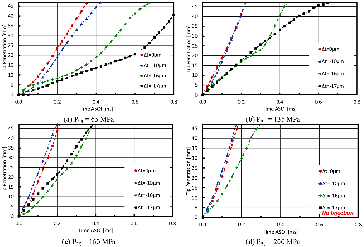
To quantitatively evaluate spray development, spray tip penetration was measured using image analysis, as defined in Figure 2b. Spray tip penetration is a key macroscopic parameter for characterizing spray behavior, particularly during the early stage of injection, where needle motion strongly influences fuel discharge dynamics. Previous studies have demonstrated that variations in needle motion affect needle lift, which in turn governs spray momentum, atomization, and breakup processes during injection [26]. In this study, spray tip penetration was measured for various injection pressures and upper shim thicknesses, and the resulting penetration histories are presented in Figure 5. The results show clear agreement with the qualitative observations obtained from high-speed spray imaging and the variability between repeated measurements was small and did not affect the observed trends. Specifically, the penetration curves exhibit distinct grouping according to shim thickness. The thinner shim cases (Δt = −16 μm and −17 μm) are clearly separated from the thicker and baseline configurations (Δt = −10 μm and 0 μm), indicating a systematic influence of shim thickness on spray development. For a given time after the start of injection (ASOI), a thinner shim results in shorter spray tip penetration, indicating reduced spray penetration velocity. In other words, decreasing shim thickness leads to slower spray penetration, which can be attributed to modified needle lift dynamics and a reduction in effective injection momentum. As injection pressure increases, the difference in spray tip penetration among the various shim thicknesses becomes less pronounced, suggesting that the influence of needle motion modification diminishes under higher hydraulic driving forces. Notably, for the thinner shim configurations (Δt = −16 μm and −17 μm) at low injection pressure (Pinj = 65 MPa), the spray penetration exhibits a two-stage growth behavior. In the initial stage, the spray penetrates at a relatively low velocity, followed by a transition to a higher penetration rate during the later stage of injection. This behavior suggests the presence of a mechanical or hydraulic delay associated with overcoming the initial resistance of the injector’s internal components due to shim modification. Furthermore, the observed two-stage penetration behavior may be interpreted as an unresolved pilot-like injection phase followed by a main injection phase, even though a single injection command was applied. Since only a single injection command was applied, the observed behavior does not represent an actual pilot–main injection, but rather a transient response of the injector under modified internal conditions. This behavior corresponds to the injection-rate profile, which shows a delayed and gradual rise without a clearly separated secondary peak. This suggests that the observed two-stage penetration trend is associated with transient injection dynamics rather than a distinct multi-stage injection event. This phenomenon highlights the strong coupling between injector internal dynamics and macroscopic spray behavior, particularly under low injection pressure and reduced shim thickness conditions. Further confirmation would require direct observation of a distinct two-stage injection-rate profile or additional diagnostics of needle motion.
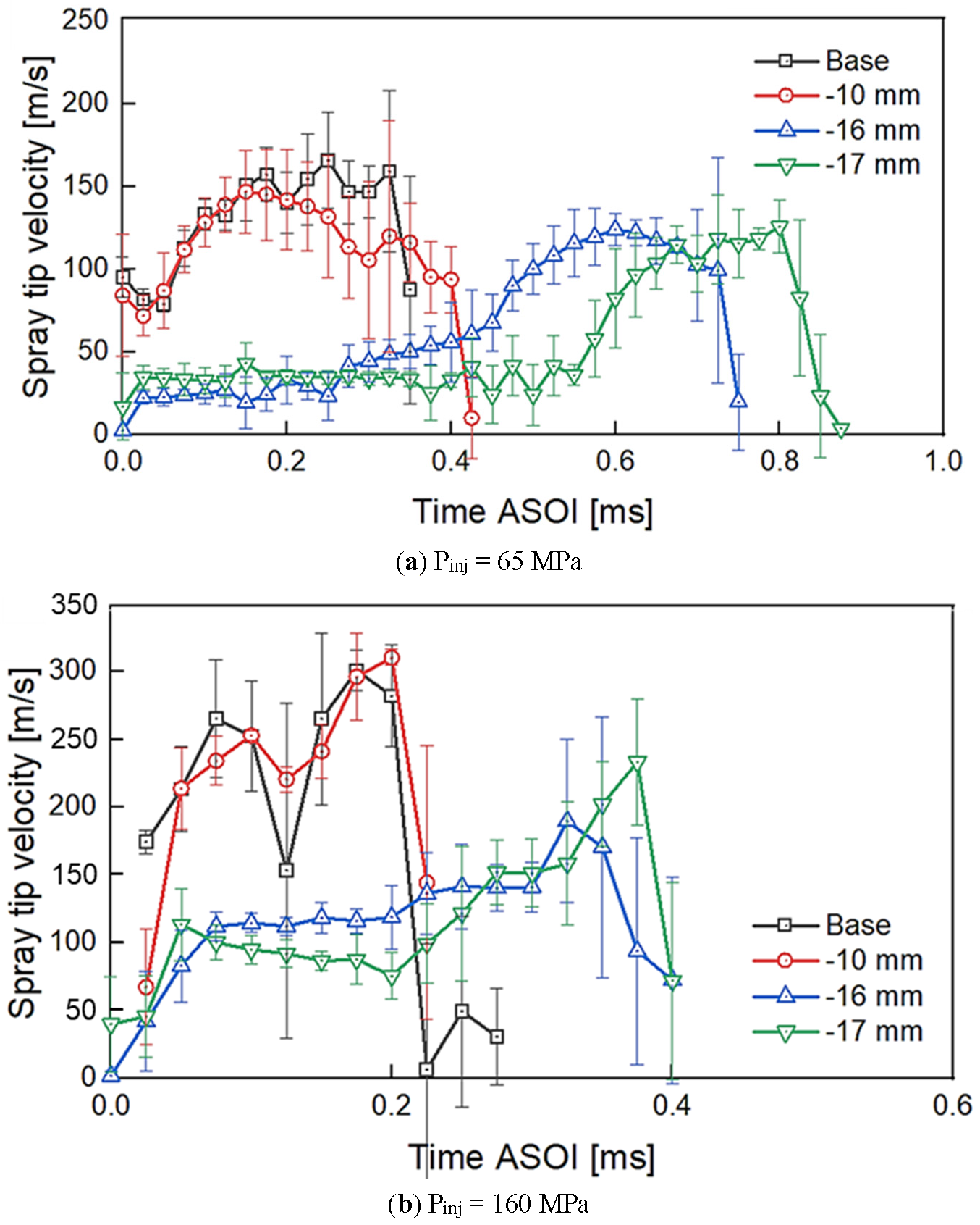
By combining the measured spray tip penetration distance with the temporal resolution of the high-speed imaging, the spray tip penetration velocity was quantitatively evaluated. Figure 6 presents the temporal evolution of spray tip penetration velocity for various injection pressures and upper shim thicknesses. Consistent with the trends observed in the high-speed spray images and spray tip penetration measurements, the spray tip penetration velocity exhibits a clear separation between the thinner shim configurations (Δt = −16 μm and −17 μm) and the thicker or baseline configurations (Δt = −10 μm and 0 μm). In general, the thinner shim cases show lower spray tip penetration velocities compared with the thicker shim cases, indicating reduced spray momentum. This trend is consistently observed across all tested injection pressures, confirming that a decrease in upper shim thickness leads to slower spray tip development. Interestingly, for the thinner shim configurations at low injection pressure (Pinj = 65 MPa), a pronounced increase in spray tip penetration velocity is observed after the initial stage of injection. In these cases, the spray tip penetration velocity increases significantly with time and can reach values that are approximately two to three times higher than those observed immediately after the start of injection. This behavior suggests a delayed but accelerated spray development, which may be associated with gradual needle lift progression and increasing effective flow area as injection proceeds. At higher injection pressures, the spray tip penetration velocity follows a similar qualitative trend to that observed under low injection pressure conditions. However, the overall magnitude of the velocity is higher due to the increased injection momentum. Despite this, the relative differences between shim thickness cases remain evident, indicating that injector internal modification through shim thickness variation continues to play a dominant role in governing spray dynamics even under high-pressure injection conditions.
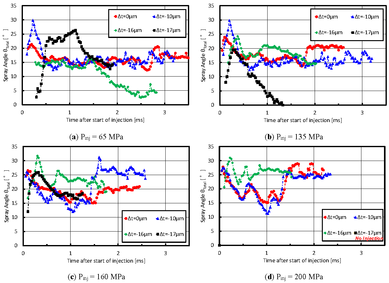
To quantitatively evaluate spray breakup and atomization behavior, the spray angle was measured using image analysis, as defined in Figure 2b. The results in Figure 7 show that the spray angle is largest during the early stage of injection for all tested conditions. This behavior is attributed to the highly transient and turbulent internal flow within the sac volume and nozzle orifice immediately after needle opening, which strongly affects the velocity vectors of the emerging liquid jet and enhances spray breakup. As the injection proceeds and the internal flow transitions toward a quasi-steady state, the spray angle gradually stabilizes and remains nearly constant. This indicates that the influence of transient internal flow structures diminishes as the needle lift and flow field become fully developed. A clear dependence of spray angle behavior on shim thickness is observed. Injectors equipped with thinner upper shims exhibit wider spray angles compared with those using thicker and default shims. Moreover, the duration over which a wide spray angle is maintained is longer for thinner shim configurations. This behavior suggests slower needle motion and a prolonged low-lift regime for thinner shims, during which unsteady internal flow and enhanced turbulence persist for a longer period. As a result, spray breakup is intensified, leading to a wider spray angle over an extended injection duration.
After evaluating the spray characteristics, it is also important to investigate the injection rate behavior of the injector following shim thickness modification. Based on the high-speed spray images, it was observed that fuel injection terminates earlier for thinner shim configurations compared with the thicker or baseline shim thickness. In addition, the spray tip penetration develops more slowly for thinner shims. These observations indicate that shim thickness significantly affects the internal injector dynamics, making a detailed examination of the injection rate necessary.
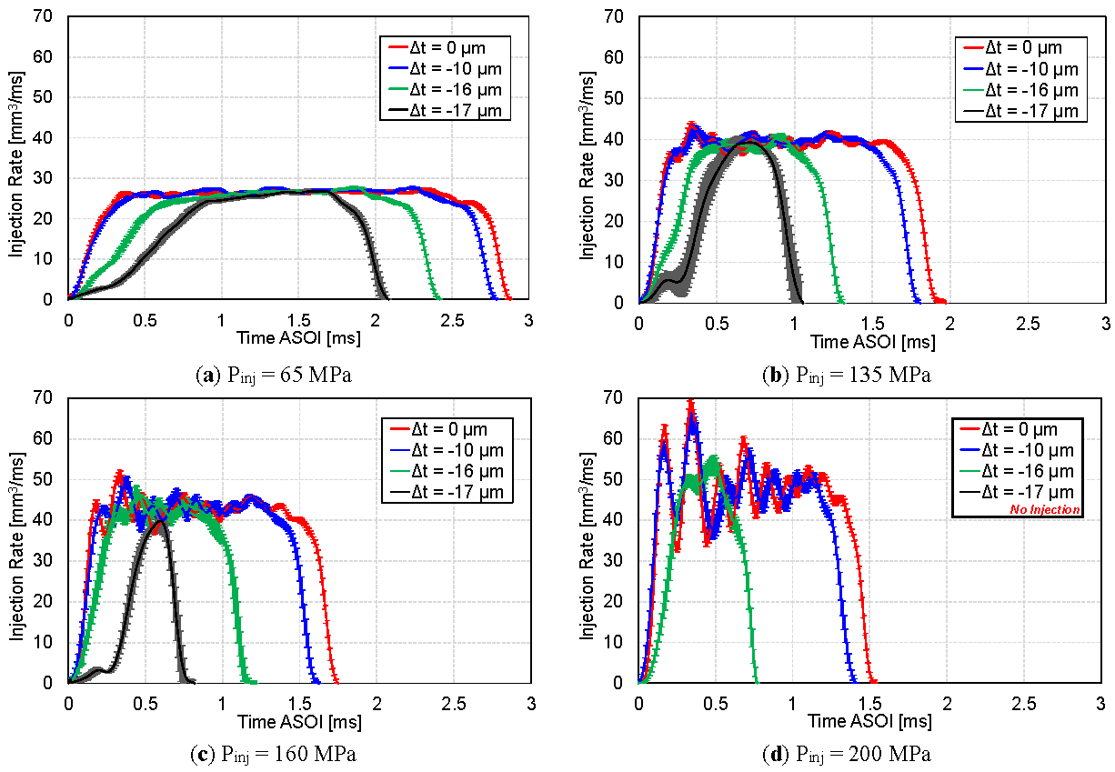
Figure 8 presents the measured injection rate profiles for various injection pressures and shim thicknesses. The results clearly show that decreasing the shim thickness leads to a shorter injection duration across all tested injection pressures. Moreover, thinner shims exhibit a noticeably slower rise in injection rate during the initial phase of injection. As a result, a longer time is required for the injection rate to reach a quasi-steady state, where a nearly constant fuel delivery rate is maintained. This delayed rate buildup directly corresponds to the slower spray tip penetration observed for thinner shim configurations. Consistent with the spray penetration results, a clear separation is observed between the thinner shim configurations (Δt = −16 μm and −17 μm) and the thicker or baseline configurations (Δt = −10 μm and 0 μm) in terms of injection rate behavior. The thinner shims show shortened effective injection periods, indicating a lower overall injection momentum. With increasing injection pressure, the injection rate rises more rapidly at the start of injection and decreases more sharply at the end of injection for all shim thicknesses. It should be noted that, at higher injection pressures, the electrical injection pulse duration was shortened to achieve a comparable injected fuel quantity. Despite this adjustment, the injection duration for thinner shim configurations remains significantly shorter than that of the thicker or baseline shims. Furthermore, under the highest injection pressure condition of 200 MPa, no observable spray was detected in the high-speed images, and no measurable injection-rate signal was obtained for the thinnest shim configuration (Δt = −17 μm). Several possible mechanisms may explain this behavior. First, the needle may not open sufficiently due to the reduced shim thickness, resulting in an effective blockage of the flow passage. Second, the needle lift may be below a critical threshold required for stable fuel discharge. Third, hydraulic losses may prevent the development of sufficient flow through the nozzle. However, since internal injector dynamics were not directly measured in the present study, these mechanisms should be considered as plausible interpretations rather than definitive explanations. This condition highlights a practical limitation of injector internal modification, indicating that excessive reduction in shim thickness, particularly under high injection pressure, may lead to failure of effective fuel injection. This finding is important for defining the operational limits of such modification strategies. It also suggests a strong coupling between mechanical constraint and hydraulic response in high-pressure injection conditions.
4. Discussion
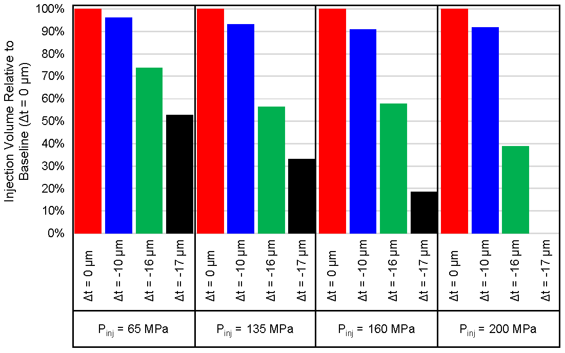
One direct consequence of the shortened injection duration caused by shim thickness reduction is a decrease in the total injected fuel volume relative to the intended amount. This reduction has a direct impact on the engine’s potential power output, as the injected fuel quantity is a primary determinant of the released chemical energy. Consequently, to achieve the same injected fuel mass as the baseline injector configuration, a longer electrical injection pulse is required when thinner shims are employed. Figure 9 presents the injected fuel volume expressed as a percentage relative to the baseline configuration (Δt = 0 μm) for various injection pressures and shim thicknesses. The results clearly indicate that reducing the shim thickness leads to a significant decrease in injected fuel volume. This reduction becomes more pronounced as the injection pressure increases, reflecting the combined effects of shortened injection duration and altered needle dynamics under high-pressure conditions. At higher injection pressures, although the instantaneous injection rate increases, the effective injection period for thinner shim configurations becomes considerably shorter, resulting in a net reduction in total injected fuel volume. These findings confirm that shim thickness modification not only affects spray development and injection rate characteristics but also directly influences fuel delivery control. Therefore, compensation through an extended injection pulse duration is essential when thinner shims are used to maintain an equivalent injected fuel quantity compared with the baseline injector.
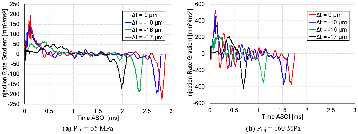
As shown in the injection rate measurements, both the rise and decay of the injection rate become more gradual as the upper shim thickness is reduced. To quantitatively evaluate this deceleration behavior, the injection rate gradient, defined as the time derivative of the injection rate (i.e., the slope of the injection-rate curve), was calculated, and the results are presented in Figure 10. At the start of injection, the injection rate gradient is noticeably higher for the baseline and thicker shim configurations (Δt = 0 μm and −10 μm), indicating a rapid increase in fuel delivery immediately after needle opening. In contrast, for the thinner shim cases (Δt = −16 μm and −17 μm), the initial injection rate gradient is significantly lower and converges to similar values, demonstrating a slower buildup of injection rate. This behavior is likely to reflect reduced or delayed needle lift, which limits the effective flow area during the early injection phase and prolongs the transient opening process. At the end of injection, the injection rate gradient also tends to be slightly lower for thinner shim configurations, although the difference is less pronounced than that observed at the start of injection. This suggests that shim thickness primarily influences the needle opening dynamics rather than the closing process, which is likely governed more by solenoid de-energizing and hydraulic pressure decay.
With increasing injection pressure, the same general trend is maintained across all shim thicknesses. Higher injection pressure leads to steeper injection rate gradients overall, reflecting the stronger hydraulic force acting on the needle. However, at the end of injection, the gradients converge to similar values regardless of shim thickness, implying that the needle closing behavior becomes dominated by pressure-driven flow collapse and actuator response rather than by mechanical preload variations introduced by the shim. Overall, these results demonstrate that reducing shim thickness significantly alters the transient injection dynamics, particularly during the opening phase, by slowing the rate at which the injector reaches a quasi-steady injection condition. This behavior is consistent with the observed delays in spray development, reduced spray tip penetration, and shortened effective injection duration for thinner shim configurations discussed in the previous sections.
As also observed in Figure 8, thinner shim cases exhibit a more gradual rise in injection rate, which is directly reflected in Figure 10 by the lower gradients at the start of injection. A lower gradient indicates a slower needle opening process and a more gradual development of flow through the nozzle, whereas a higher gradient reflects a more rapid needle response and faster establishment of the quasi-steady injection rate. Similarly, differences in the gradient at the end of injection correspond to the rate at which the injection is terminated, as observed in the falling edge of the injection-rate profiles.
The shape of the diesel injection rate is a critical parameter governing in-cylinder mixture formation, combustion phasing, and emissions formation. A slower injection rate rise, as observed for thinner shim configurations, can suppress excessive initial fuel momentum and modify early spray development, potentially reducing wall impingement and local fuel-rich regions. Conversely, a rapid injection rate rise, typical of thicker or baseline shim configurations, promotes stronger spray penetration and faster air–fuel mixing, which can enhance combustion efficiency but may increase NOx formation due to higher local temperatures. Therefore, optimizing the injection rate shape requires a careful balance between competing emission pathways, particularly the well-known NOx–soot trade-off. Previous studies have shown that tailored injection rate profiles, such as rate shaping with moderated initial slopes or shortened effective injection durations, can reduce soot formation while maintaining acceptable thermal efficiency, although excessive rate suppression may lead to incomplete combustion and higher hydrocarbon emissions [46,47,48,49]. Specifically, a slower injection rate rise and reduced spray penetration may influence local air–fuel mixing, potentially reducing soot formation due to improved mixture homogeneity [50,51,52,53]. Similarly, variations in injection timing and rate shaping may affect peak combustion temperature, which is closely related to NOx formation [46,47,54,55]. Shorter injection duration and reduced fuel quantity may also influence overall combustion efficiency and CO₂ emissions [56].
The interpretations regarding needle motion, internal flow behavior, and hydraulic response are based on indirect evidence derived from injection rate measurements and spray visualization. In the present study, parameters such as needle lift, solenoid current, and internal flow structures were not directly measured. Therefore, the proposed mechanisms should be considered as plausible interpretations rather than definitive conclusions. Future work involving direct diagnostics, such as needle lift measurement or internal flow visualization, is required to validate these mechanisms. Furthermore, the present analysis is limited to macroscopic spray characteristics, including spray penetration and spray angle. Microscopic spray features such as droplet size distribution, primary and secondary breakup processes, liquid length, and vapor-phase behavior were not measured. Therefore, conclusions regarding atomization quality and mixture formation cannot be directly drawn from the current results. Future work incorporating advanced diagnostics, such as phase Doppler interferometry or laser-induced fluorescence, is required to provide a more comprehensive understanding of spray atomization and evaporation processes.
The experiments were performed under low-pressure, non-evaporating, and non-reacting ambient conditions, which differ significantly from in-cylinder diesel engine environments. Therefore, the present results represent fundamental spray behavior governed primarily by injection dynamics and ambient gas interaction at low density. The extrapolation of these findings to engine-relevant conditions, where high pressure, high temperature, evaporation, and combustion occur, should be made with caution. Future investigations under elevated ambient pressure and temperature are necessary to evaluate the impact of injector internal modification on evaporating sprays, combustion processes, and emission formation. In addition, the injection duration was varied with injection pressure to maintain a comparable injected fuel quantity. As a result, the effects of injection pressure are inherently coupled with changes in injection duration in the present study. Therefore, the observed differences in spray and injection rate behavior should be interpreted as the combined effect of these parameters, rather than as a result of injection pressure alone. A more rigorous separation of these effects would require additional experiments under fixed command duration as well as equal-injected-quantity conditions, which is recommended for future work.
No combustion or emission measurements were conducted in this study; therefore, the discussion of emission characteristics is based on inferred implications from spray and injection behavior. Further investigation under engine-relevant conditions, including combustion and emission measurements, is necessary to validate these implications. It should be noted that the present results are obtained using a specific commercially available solenoid injector with a fixed nozzle design and fuel type. Variations in injector architecture, such as piezoelectric actuators, different nozzle geometries, or alternative fuels, may lead to different responses to shim thickness modification. Therefore, the observed trends should not be considered universally applicable, and further studies across different injector configurations are required to generalize the findings.
The combined results from injection rate measurements and spray visualization indicate that mechanical adjustments at the injector level, such as shim thickness modification, alter the injector needle dynamics, which in turn govern the injection rate profile and spray formation. This provides an additional degree of freedom for influencing injection rate shaping without altering electronic control strategies. By systematically understanding and manipulating the injection rate shape through internal injector configuration, engineers can more precisely tailor spray development and combustion behavior to specific engine operating conditions. This approach offers a promising pathway for improving diesel engine performance while simultaneously reducing harmful emissions, contributing to the development of more efficient and environmentally sustainable combustion systems.
5. Conclusions
The present study demonstrates that modifications to internal injector components—specifically variations in the upper shim thickness—can significantly influence fuel injection dynamics and the resulting diesel spray characteristics. Altering the shim thickness directly affects injector needle motion, which in turn modifies the temporal evolution of the injection rate, including injection delay, rate-of-rise, quasi-steady injection duration, and injection termination behavior. These changes ultimately govern macroscopic spray development and fuel delivery characteristics. The main findings of this study can be summarized as follows:
Overall, these results highlight the strong coupling between injector internal mechanical configuration and diesel spray behavior. The findings suggest that mechanical tuning of injector components, such as shim thickness adjustment, offers a viable method for controlling injection rate shaping and spray development without modifying electronic control parameters. This approach provides valuable insight for injector design optimization and may contribute to improved combustion control, enhanced engine efficiency, and reduced emissions in diesel engine applications.
Author Contributions
R.H.P.: conceptualization, methodology, software, validation, formal analysis, investigation, data curation, writing—original draft, visualization; W.H.: conceptualization, methodology, validation, writing—reviewing and editing, supervision, project administration, funding acquisition; Y.S.: investigation, visualization, writing—reviewing and editing. All authors have read and agreed to the published version of the manuscript.
Funding
This research received no external funding.
Institutional Review Board Statement
Not applicable.
Informed Consent Statement
Not applicable.
Data Availability Statement
Not applicable.
Conflicts of Interest
Given his role as an Editorial Board Member, Weidi Huang had no involvement in the peer-review process of this paper and had no access to information regarding its review process. Full responsibility for the editorial handling of this manuscript was delegated to another editor of the journal.
Use of AI and AI-Assisted Technologies
During the preparation of this work, the authors used ChatGPT to assist in language refinement and improvement of clarity and readability. After using this tool, the authors reviewed and edited the content as needed and take full responsibility for the content of the published article.
Abbreviations
|
ASOE |
After start of energizing |
|
ASOI |
After start of injection |
|
Pinj |
Fuel injection pressure |
|
x |
Distance from the upper side of the nozzle hole axis to the upper spray boundary measured at 12 mm downstream of the nozzle exit |
|
y |
Distance from the lower side of the nozzle hole axis to the lower spray boundary measured at 12 mm downstream of the nozzle exit |
|
θtotal |
Total spray angle |
|
θU |
Upper spray angle |
|
θL |
Lower spray angle |
|
Δt |
Shim thickness difference relative to the baseline (default) shim |
References
- 1.
Xu, H.; Li, L.; Yao, M. A Study on the Influence of Geometric Parameters of Stepped Combustion Chamber on Heavy Duty Diesel Engines. Int. J. Automot. Technol. 2025. https://doi.org/10.1007/s12239-025-00371-0.
- 2.
Aris, M.M.A.M.M.; Soid, S.N.M.; Azid, I.A. Development of an Optical Measurement Test Rig for Fuel Spray Characteristics Study of a Diesel Direct Injection System—An Experimental Approach. In Advanced Structured Materials; Springer: Cham, Switzerland, 2023; pp. 67–73. https://doi.org/10.1007/978-3-031-29348-1_8.
- 3.
Cardona, S.; Payri, R.; Salvador, F.J.; Gimeno, J. Effects of Varying the Liquid Fuel Type and Air Co-Flow Conditions on the Microscopic Spray Characteristics in an Atmospheric Annular Co-Flow Spray Burner. Fuel 2023, 335, 127018. https://doi.org/10.1016/j.fuel.2022.127018.
- 4.
Gopinath, S.; Devan, P.K.; Sabarish, V.; Babu, B.S.; Sakthivel, S.; Vignesh, P. Effect of Spray Characteristics Influences Combustion in DI Diesel Engine—A Review. Mater. Today Proc. 2020, 33, 52–65. https://doi.org/10.1016/j.matpr.2020.03.130.
- 5.
Wang, X.R.; Li, H.M.; Li, G.X.; Huo, H.B. Experimental Investigation of Fuel-Spray Droplet Size Distribution Relating to Cold Start Conditions in Diesel Engines. J. Energy Eng. 2025, 151, 04025012. https://doi.org/10.1061/JLEED9.EYENG-6037.
- 6.
Jin, T.; Wang, C.; Moro, A.; Roell, A.; Wu, X.; Luo, F. The Influence of Needle Eccentric Motion on Injection and Spray Characteristics of a Two-Layered Eight-Hole Diesel Injector. Proc. Inst. Mech. Eng. Part D J. Automob. Eng. 2024, 238, 3308–3327. https://doi.org/10.1177/09544070231179779.
- 7.
Lahane, S.; Deshmukh, P.W.; Nandgaonkar, M.R. Mathematical Modeling of Injection and Spray Characteristics of a Diesel Engine: A Review. In Energy, Environment, and Sustainability; Springer: Singapore, 2022; pp. 29–55. https://doi.org/10.1007/978-981-16-8618-4_3.
- 8.
Feng, Z.; Tang, C.; Yin, Y.; Zhang, P.; Huang, Z. Time-Resolved Droplet Size and Velocity Distributions in a Dilute Region of a High-Pressure Pulsed Diesel Spray. Int. J. Heat Mass Transf. 2019, 133, 745–755. https://doi.org/10.1016/j.ijheatmasstransfer.2018.12.147.
- 9.
Cheng, Q.; Ahmad, Z.; Grahn, V.; Hyvönen, J.; Martti, L.; Kaario, O. Multi-Scale Optical Diagnostics for Marine Diesel Spray. Energy 2025, 317, 134624. https://doi.org/10.1016/j.energy.2025.134624.
- 10.
Zhu, H.; Guo, X.; Di, Z. Effects of Injector Parameters on Combustion and Emissions of Diesel Engine in Low Temperature Environment. Energy Sources Part A: Recovery Util. Environ. Eff. 2025, 47, 10001–10018. https://doi.org/10.1080/15567036.2025.2496294.
- 11.
Petrea, N.D.; Bujoreanu, C. Importance of Fuel Injection System for Low Emissions, Combustion Noise and Low Fuel Consumption. IOP Conf. Ser. Mater. Sci. Eng. 2018, 444, 042020. https://doi.org/10.1088/1757-899X/444/4/042020.
- 12.
Kuronita, T.; Sakai, T.; Queck, D.; Puts, R.; Visser, S.; Herrmann, O.; Nishijima, Y. A Study of Dynamic Combustion Control for High Efficiency Diesel Engine. In Proceedings of the WCX SAE World Congress Experience, Detroit, MI, USA, 21–23 April 2020. https://doi.org/10.4271/2020-01-0297.
- 13.
Agarwal, A.K.; Gopal, J.; Nikhil, G.; Singh, A.P. (Eds.) Advanced Engine Diagnostics; Energy, Environment, and Sustainability Series; Springer: Singapore, 2019. https://doi.org/10.1007/978-981-13-3275-3.
- 14.
Marri, V.B.; Kotha, M.M.; Gaddale, A.P.R. Experimental Investigations on the Influence of Higher Injection Pressures and Retarded Injection Timings on a Single Cylinder CRDi Diesel Engine. Int. J. Ambient Energy 2021, 42, 444–457. https://doi.org/10.1080/01430750.2018.1540017.
- 15.
Hoang, A.T. Applicability of Fuel Injection Techniques for Modern Diesel Engines. AIP Conf. Proc. 2020, 2207, 020003. https://doi.org/10.1063/5.0000133.
- 16.
Selvaraj, K. A Comprehensive Review: Role of Fuel Injection Methodologies on Performance Enhancement and Mitigation of Emissions in the Diesel Engine. Int. J. Oil Gas Coal Technol. 2024, 36, 219–243. https://doi.org/10.1504/IJOGCT.2024.140281.
- 17.
Hao, J.; Yang, K.; Ma, H. Numerical Simulation of Improving Diesel Engine Emission Pollutants through Fuel Injection Strategy. In Proceedings of the 13th Annual International Conference on Material Science and Environmental Engineering, Wuhan, China, 25–27 July 2025. https://doi.org/10.1117/12.3085990.
- 18.
Singh, H.; Kutkut, A.; Pal, P.; Kumar, S.; Li, H. Numerical Investigation of the Combustion Process and Emissions Formation in a Heavy-Duty Diesel Engine Featured with Multi-Pulse Fuel Injection. SAE Int. J. Adv. Curr. Pract. Mobil. 2024, 7, 1739–1761. https://doi.org/10.4271/2024-01-4285.
- 19.
Chacko, N.; Jeyaseelan, T. Experimental Study of Multiple Injection Scheduling for Smoke—NOx Tradeoff in a Twin Cylinder Turbo Charged CRDI Engine. AIP Conf. Proc. 2019, 2161, 020019. https://doi.org/10.1063/1.5127600.
- 20.
Wang, X.; Huang, Z.; Kuti, O.A.; Zhang, W.; Nishida, K. Experimental and Analytical Study on Biodiesel and Diesel Spray Characteristics under Ultra-High Injection Pressure. Int. J. Heat Fluid Flow 2010, 31, 659–666. https://doi.org/10.1016/j.ijheatfluidflow.2010.03.006.
- 21.
Xuan, T.; Sun, Z.; EL-Seesy, A.I.; Mi, Y.; Zhong, W.; He, Z.; Wang, Q.; Sun, J.; El-Batsh, H.M.; Cao, J. An Optical Study on Spray and Combustion Characteristics of Ternary Hydrogenated Catalytic Biodiesel/Methanol/n-Octanol Blends; Part II: Liquid Length and in-Flame Soot. Energy 2021, 227, 120543. https://doi.org/10.1016/j.energy.2021.120543.
- 22.
Wang, C.; Adams, M.; Luo, T.; Jin, T.; Luo, F.; Gavaises, M. Hole-to-Hole Variations in Coupled Flow and Spray Simulation of a Double-Layer Multi-Holes Diesel Nozzle. Int. J. Engine Res. 2021, 22, 3233–3246. https://doi.org/10.1177/1468087420963986.
- 23.
Wang, Z.; Ding, H.; Wyszynski, M.L.; Tian, J.; Xu, H. Experimental Study on Diesel Fuel Injection Characteristics under Cold Start Conditions with Single and Split Injection Strategies. Fuel Process. Technol. 2015, 131, 213–222. https://doi.org/10.1016/j.fuproc.2014.10.003.
- 24.
Ritter, D.; Korkmaz, M.; Pitsch, H.; Abel, D.; Albin, T. Optimization-Based Fuel Injection Rate Digitalization for Combustion Rate Shaping. In Proceedings of the 2019 American Control Conference (ACC), Philadelphia, PA, USA, 10–12 July 2019; pp. 5103–5110. https://doi.org/10.23919/acc.2019.8815184.
- 25.
Viera, J.P.; Payri, R.; Swantek, A.B.; Duke, D.J.; Sovis, N.; Kastengren, A.L.; Powell, C.F. Linking Instantaneous Rate of Injection to X-Ray Needle Lift Measurements for a Direct-Acting Piezoelectric Injector. Energy Convers. Manag. 2016, 112, 350–358. https://doi.org/10.1016/j.enconman.2016.01.038.
- 26.
Pratama, R.H.; Huang, W.; Moon, S. Unveiling Needle Lift Dependence on Near-Nozzle Spray Dynamics of Diesel Injector. Fuel 2021, 285, 119088. https://doi.org/10.1016/j.fuel.2020.119088.
- 27.
Kang, S.; Lee, S.; Hong, D.; Bae, C. Effects of Nozzle Orifice Diameter and Hole Number on Diesel Combustion and Engine Performance. Int. J. Automot. Technol. 2022, 23, 481–494. https://doi.org/10.1007/s12239-022-0044-8.
- 28.
Huang, W.; Moon, S.; Gao, Y.; Wang, J.; Ozawa, D.; Matsumoto, A. Hole Number Effect on Spray Dynamics of Multi-Hole Diesel Nozzles: An Observation from Three- to Nine-Hole Nozzles. Exp. Therm. Fluid Sci. 2019, 102, 387–396. https://doi.org/10.1016/j.expthermflusci.2018.12.022.
- 29.
Zhang, X.; Moon, S.; Gao, J.; Dufresne, E.M.; Fezzaa, K.; Wang, J. Experimental Study on the Effect of Nozzle Hole-to-Hole Angle on the Near-Field Spray of Diesel Injector Using Fast X-Ray Phase-Contrast Imaging. Fuel 2016, 185, 142–150. https://doi.org/10.1016/j.fuel.2016.07.114.
- 30.
Andriotis, A.; Gavaises, M.; Arcoumanis, C. Vortex Flow and Cavitation in Diesel Injector Nozzles. J. Fluid Mech. 2008, 610, 195–215. https://doi.org/10.1017/S0022112008002668.
- 31.
Sou, A.; Hosokawa, S.; Tomiyama, A. Effects of Cavitation in a Nozzle on Liquid Jet Atomization. Int. J. Heat Mass Transf. 2007, 50, 3575–3582. https://doi.org/10.1016/j.ijheatmasstransfer.2006.12.033.
- 32.
Arcoumanis, C.; Whitelaw, J.H. Is Cavitation Important in Diesel Engine Injector? In Thermo- and Fluid-Dynamic Processes in Diesel Engines; Whitelaw, J.H., Payri, F., Arcoumanis, C., Desantes, J.-M., Eds.; Springer: Berlin/Heidelberg, Germany, 2002; pp. 145–157.
- 33.
Pratama, R.H.; Sou, A.; Katsui, T.; Nishio, S. String Cavitation in a Fuel Injector. Atomization Sprays 2017, 27, 493–506. https://doi.org/10.1615/AtomizSpr.2016016276.
- 34.
Moon, S.; Huang, W.; Wang, J. First Observation and Characterization of Vortex Flow in Steel Micronozzles for High-Pressure Diesel Injection. Exp. Therm. Fluid Sci. 2019, 105, 342–348. https://doi.org/10.1016/j.expthermflusci.2019.04.018.
- 35.
Hayashi, T.; Suzuki, M.; Ikemoto, M. Visualization of Internal Flow and Spray Formation with Real Size Diesel Nozzle. In Proceedings of the 12th International Conference on Liquid Atomization and Spray Systems (ICLASS 2012), Heidelberg, Germany, 2–6 September 2012.
- 36.
Hayashi, T.; Suzuki, M.; Ikemoto, M. Effects of Internal Flow in a Diesel Nozzle on Spray Combustion. Int. J. Engine Res. 2013, 14, 646–654. https://doi.org/10.1177/1468087413494910.
- 37.
Watanabe, H.; Nishikori, M.; Hayashi, T.; Suzuki, M.; Kakehashi, N.; Ikemoto, M. Visualization Analysis of Relationship between Vortex Flow and Cavitation Behavior in Diesel Nozzle. Int. J. Engine Res. 2015, 16, 5–12. https://doi.org/10.1177/1468087414562459.
- 38.
Pratama, R.H.; Huang, W.; Gao, Y. Investigation of Diesel Spray Characteristics from Injectors with Asymmetric Hole Distribution. Fuel 2025, 385, 134068. https://doi.org/10.1016/j.fuel.2024.134068.
- 39.
Prasetya, R.; Sou, A.; Moon, S.; Pratama, R.H.; Wada, Y.; Yokohata, H. X-ray Phase Contrast Imaging of Cavitation and Discharged Liquid Jet in Nozzles with Various Sizes. At. Sprays 2019, 29, 59–78. https://doi.org/10.1615/atomizspr.2019029661.
- 40.
Prasetya, R.; Sou, A.; Moon, S.; Pratama, R.H.; Wada, Y.; Yokohata, H. In-Nozzle Cavitation and Discharged Liquid Jet during Transient Injection Process. At. Sprays 2019, 29, 123–141. https://doi.org/10.1615/atomizspr.2019030077.
- 41.
Gao, Y.; Huang, W.; Pratama, R.H.; Wang, J. Transient Nozzle-Exit Velocity Profile in Diesel Spray and Its Influencing Parameters. Int. J. Automot. Manuf. Mater. 2022, 1, 1–12.
- 42.
Zepf, A.; Gelner, A.D.; Härtl, M.; Jaensch, M. 3D-CFD-Based Optimization of Piston Geometry, Injector Nozzle Design, and Injection Strategy for the Alternative Diesel Fuel Oxymethylene Ether (OME). Fuel 2026, 406, 136995. https://doi.org/10.1016/j.fuel.2025.136995.
- 43.
Li, M.; Mao, Y.; Chao, C.; Wei, Y.; Fan, L.; Li, Y. Nonlinear Characteristics of Pilot Fuel Injection Quantity in Low-Carbon Fuel Combustion Systems. Energy Convers. Manag. 2026, 356, 121315. https://doi.org/10.1016/j.enconman.2026.121315.
- 44.
Wang, Z.; Liang, T.; Jiang, C. Internal Flow Characteristics and Vortex Evolution of Fuel Injector with Dynamic Needle Oscillation. Flow Turbul. Combust. 2026, 116, 44. https://doi.org/10.1007/s10494-026-00739-x.
- 45.
Chen, J.; Liu, L.; Zhao, B. Injection Mechanism in Asymmetric Fuel Injector in Diesel Engine Based on Multiphase Flow-Cavitation Coupling Model. Flow Meas. Instrum. 2026, 109, 103248. https://doi.org/10.1016/j.flowmeasinst.2026.103248.
- 46.
Mohan, B.; Yang, W.; Yu, W.; Tay, K.L.; Chou, S.K. Numerical Investigation on the Effects of Injection Rate Shaping on Combustion and Emission Characteristics of Biodiesel Fueled CI Engine. Appl. Energy 2015, 160, 737–745. https://doi.org/10.1016/j.apenergy.2015.08.034.
- 47.
Bai, F.; Zhang, Z.; Du, Y.; Zhang, F.; Peng, Z. Effects of Injection Rate Profile on Combustion Process and Emissions in a Diesel Engine. J. Combust. 2017, 2017, 9702625. https://doi.org/10.1155/2017/9702625.
- 48.
Chen, J.; Shi, G.; Wu, J.; Cao, C.; Zhou, L.; Xu, W.; Wang, S.; Li, X. Combustion and Emission Characteristics of a Diesel Engine with a Variable Injection Rate. Appl. Sci. 2024, 14, 4941. https://doi.org/10.3390/app14114941.
- 49.
Niculae, A.L.; Chiriac, R.; Racovitza, A. Effects of Injection Rate Shape on Performance and Emissions of a Diesel Engine Fuelled by Diesel and Biodiesel B20. Appl. Sci. 2022, 12, 1333. https://doi.org/10.3390/app12031333.
- 50.
Jang, J.; Ra, S.; Choi, M.; Park, J.; Park, S. Effects of Injector Nozzle Hole Number and Hydraulic Flow Rate on Combustion and Emission Characteristics in a Heavy Duty Diesel Engine. In Proceedings of the ICLASS 2018—14th International Conference on Liquid Atomization and Spray Systems, Chicago, IL, USA, 22–26 July 2018.
- 51.
Matsuura, K.; Suzuki, O.; Kato, A. In-Cylinder Optical Investigation of Combustion Behavior on a Fast Injection Rate Diesel Common Rail Injector. SAE Int. J. Fuels Lubr. 2012, 5, 88–97. https://doi.org/10.4271/2011-01-1821.
- 52.
Sun, T.; Su, W.-H.; Guo, H.-S. Development of Quantitative Calibration Method for Planar Laser Induced Exciplex Fluorescence Technique and Application on the Diesel Spray Characteristics II: Quantitative Analysis the Influence of Injection and Ambient Parameters on Spray Characteristics. Neiranji Xuebao Trans. CSICE 2010, 28, 10–19.
- 53.
Cung, K.; Bitsis, D.C.; Briggs, T.; Kalaskar, V.; Abidin, Z.; Shah, B.; Miwa, J. Effect of Micro-Hole Nozzle on Diesel Spray and Combustion. In Proceedings of the WCX World Congress Experience, Detroit, MI, USA, 10 April 2018. https://doi.org/10.4271/2018-01-0301.
- 54.
Benajes, J.; Molina, S.; De Rudder, K.; Rente, T. Influence of Injection Rate Shaping on Combustion and Emissions for a Medium Duty Diesel Engine. J. Mech. Sci. Technol. 2006, 20, 1436–1448. https://doi.org/10.1007/BF02915967.
- 55.
Mei, D.; Tu, L.; Yue, S.; Adu-Mensah, D.; Jiang, S. Simulation of Combustion Process and Pollutant Generation in a PCCI Diesel Engine with Adaptable Multiple Injection. J. Energy Eng. 2018, 144, 04018024. https://doi.org/10.1061/(ASCE)EY.1943-7897.0000568.
- 56.
Herfatmanesh, M.R.; Zhao, H. Experimental Investigation of Hydraulic Effects of Two-Stage Fuel Injection on Fuel-Injection Systems and Diesel Combustion in a High-Speed Optical Common-Rail Diesel Engine. Int. J. Engine Res. 2014, 15, 48–65. https://doi.org/10.1177/1468087412458100.


This work is licensed under a Creative Commons Attribution 4.0 International License.
 Suite 4002 Level 4, 447 Collins Street, Melbourne, Victoria 3000, Australia
 General Inquiries: info@sciltp.com