Improving the thermal efficiency of engines and the application of alcohols are crucial for achieving carbon neutrality goals. This article investigates the effects of different dissociated methanol gas injection pressures on the performance of methanol engines under lean combustion conditions, aiming to improve combustion, performance, and emissions. It was found that the increase in environmental pressure would make the shape of the dissociated methanol gas jet more concentrated and shorten the jet penetration distance. When the time is 0.9 ms, the environmental pressure increases from 0.1 MPa to 0.3 MPs, 0.5 MPa, and 0.7 MPa, respectively. The jet penetration distance is shortened by 18.9 mm, 32.8 mm, and 37.4 mm, respectively. In addition, the increase in injection pressure will affect the development of mixture stratification and cause NOx emissions to first increase and then decrease. However, the CO, HC, CH3OH, and CH2O emissions showed the opposite trend. When the injection pressure exceeds 1 MPa, the direction of hydrogen stratification shifts from the x-axis to the y-axis. When the dissociated methanol gas injection pressure is 1 MPa, the in-cylinder pressure, peak cylinder temperature, and NOx emissions all reach their maximum values. The emissions of CO, HC, CH3OH, and CH2O are minimized.
- Open Access
- Article
Simulation Study on the Influence of Direct Injection Pressure on the Performance of Dissociated Methanol Gas on Lean Burn Methanol Engine
- Xianglong Meng 1,
- Fangxi Xie 1,
- Jiaquan Duan 2,
- Mingli Liu 2,
- Cheng Zhang 2,
- Xiangyang Wang 1,
- Zhaohui Jin 1,*
Author Information
Received: 09 Dec 2025 | Revised: 16 Apr 2026 | Accepted: 18 May 2026 | Published: 04 Jun 2026
Abstract
Keywords
dissociated methanol gas | lean burn | injection pressure | methanol
1. Introduction
With the rapid development of the automotive industry, the climate problems caused by carbon emissions are becoming increasingly severe. With the implementation of carbon neutrality policies worldwide, the high thermal efficiency of engines and the application of low-carbon or carbon-neutral fuels are receiving increasing attention. Compared to gasoline, alcohols are oxygen-containing fuels that can effectively reduce harmful emissions. In addition, the renewability of alcohols is one of their main advantages as alternative fuels.
Alcohols, as renewable fuels, have received close attention from scholars around the world. Among them, methanol is the most concerning. Because it has lower emissions and higher combustion efficiency. In addition, methanol has a high oxygen content, which can effectively reduce greenhouse gas and air pollutant emissions. In addition, methanol is a low-carbon renewable fuel that can be produced through biomass conversion or by using carbon dioxide and hydrogen as raw materials. This is also an important direction for the future development of methanol to achieve zero carbon emissions throughout its entire lifecycle. This indicates that methanol has great potential for application as a substitute for traditional fossil fuels.
The research on methanol as an engine fuel has been widely carried out. Liu et al. [1] studied the effect of adding methanol on combustion and performance of gasoline engines at different compression ratios. It was found that when the compression ratio exceeded 13, adding methanol could increase efficiency by 18–23%. Zhang et al. [2] studied the effect of injection strategy on the combustion performance and stability of methanol-gasoline engines. The results showed that when using M20 as fuel, a direct injection and intake injection ratio of 8:2 could reduce particulate matter emissions by 20% and achieve optimal combustion stability and IMEP. Mokhtar et al. [3] found that adding methanol to gasoline can increase power and torque by 2.4% and 0.4%, respectively. Reduce CO and NOx by at least 20% and 10%, respectively. Wang et al. [4] investigated the effects of EGR and injection pressure on combustion and emissions in methanol gasoline engines. It was found that with the increase of methanol proportion, the effective thermal efficiency and CO emissions increased. When the injection pressure is 35 MPa, and the EGR rate is 30%, the optimal performance of methanol can be achieved.
In recent years, engine technology has also developed rapidly. Among them, lean combustion technology is considered an effective way to reduce carbon emissions. Air dilution combustion technology is an effective method to improve the thermal efficiency of engines [5]. Compared with stoichiometric combustion, lean combustion technology effectively reduces pump losses and significantly lowers combustion temperature, effectively improves heat transfer losses, and thus enhances the thermal efficiency of the engine.
Zhao et al. [6] studied the effect of valve timing on methanol and ethanol engines under lean burn conditions. The results showed that compared with stoichiometric ratios, using diluted combustion increased the ITE of methanol and ethanol by 2.39% and 1.84%, respectively, and improved NOx emissions by 72.2% and 65.1%, respectively. Zhang et al. [7] studied the application effect of lean combustion technology on methanol engines and found that as lambda increases, the combustion rate decreases. When lambda is within the range of 1.3–1.6, the optimal economic zone can be achieved. Meng et al. [8] found through experimental research that compared with stoichiometric combustion, lean combustion can improve the economy of ethanol and gasoline by 12.73% and 11.96%, respectively; BSNOx decreased by 93.69% and 61.65%, respectively. Chen et al. [9] studied the effect of lean combustion on HPDI NG engines and found that when lambda reached 2.5, ITE increased to its maximum value, reaching 47.8%. At the same time, CO and particulate emissions decreased significantly, but NOx emissions increased.
However, an excessively lean mixture can lead to a decrease in engine combustion stability and an increase in NOx emissions. Mixing hydrogen can accelerate combustion and reduce cyclic variations [10]. Many researchers have explored the effect of mixed hydrogen on the performance of methanol dilution combustion.
Gong et al. [11] studied the effect of adding hydrogen on the combustion rate of methanol under lean burn conditions through simulation, and found that adding hydrogen accelerates the chemical reactions in the flame. Gong et al. [12] studied the potential improvement of combustion and emission characteristics of engines under lean burn conditions by hydrogenation. The results showed that when the hydrogen ratio was 3% and 6%, the COVIMEP could be reduced by 21.5% and 36.8%, respectively, and the CO and HC emissions could be reduced. Ji et al. [13] developed a validation model to predict the performance of hydrogen-rich methanol engines. It was found that adding hydrogen can increase flame propagation speed, reduce exhaust losses, and improve effective thermal efficiency. The above results indicate that mixed hydrogen not only extends the dilution combustion limit but also improves the combustion performance under lean burn conditions.
Although hydrogen as a fuel has the advantages of accelerating combustion speed and reducing cycle changes, its flammability, explosiveness, and low energy density pose significant obstacles to its application in engines. Online methanol reforming to produce hydrogen is an effective method to solve these problems [14]. Li et al. [15] studied the performance of a cracked methanol gas engine under lean combustion conditions and found that the introduction of dissociated methanol gas (DMG) greatly improved the engine’s economy and combustion stability. Moreover, under lean burn conditions, the improvement effect of methanol cracked gas on the BSFC of the engine, and COVIMEP was more significant. Jiang et al. [16] added 20% methanol cracking gas to gasoline engines, which improved fuel consumption, CO emissions, and HC emissions by 4.3%, 37.8%, and 32.4%, respectively. Chen et al. [17] installed a methanol steam reformer on the engine exhaust pipe and found that using the methanol reformer can save 15–25% of fuel and reduce harmful emissions by 40–50%.
In summary, hydrogen can effectively improve the stability of lean burn in methanol engines. At the same time, the application of online methanol decomposition in hydrogen production in gasoline engines and diesel engines has also been fully validated. However, research on the injection parameters of DMG has not been explored to a large extent, which severely limits its further application in improving the dilution combustion performance of methanol engines. Therefore, this article innovatively investigates the effects of direct injection DMG pressure on the combustion, performance, and emissions of methanol engines. This article aims to fill the gap in the research of direct injection pressure for DMG in engines and provide valuable perspectives for the advancement of low-carbon engine technology.
2. Methodology
2.1. Establishment of 3D Simulation Model for Engine
The engine simulation model used in this study is based on an inline four-cylinder four-stroke turbocharged spark ignition engine equipped with dual variable valve timing and an EGR system, with a displacement of 2.0 L and a compression ratio of 11.2, adopted on the test bench. The shape of the intake and exhaust passages, cylinder head, and piston are all obtained using the silicone inversion method. The geometric parts mentioned above are combined with Boolean operations to obtain the engine model. Subsequently, the valve was processed using CATIA modeling software (Converge 3.0, Convergent Science Inc, Madison, WI, USA), and a cavity with the same shape and size as the valve was established at the position of the engine valve. Thus, the geometric model used for the CONVERGE simulation in this article is obtained. Subsequently, import the geometric model of the engine into the mesh module of ANSYS software to divide the surface mesh, set the mesh size to 2 mm, and save the geometric model in STL (Stereolithography, a standard 3D file format for surface geometry) format. The mesh division diagram of the engine geometric model is shown in Figure 1.
Subsequently, import the STL format engine geometry model into CONVERGE software (CATIA V5 R20, Dassault Systèmes, Vélizy‑Villacoublay, France). Use the built-in grid diagnostic tool in CONVERGE software to diagnose grids and correct incorrect grids. In this study, the basic grid size was set to 4 mm. To ensure accurate calculation results, in addition to adaptive encryption settings, fixed encryption was also used for some structures of the model. This engine simulation model increases the overall cylinder density by 2 levels, and increases the intake and exhaust valve seats by 4 levels during the intake and exhaust processes. During the ignition process, a 2 mm spherical area near the spark plug ignition position is increased by 5 levels, and a 4 mm spherical area is increased by 4 levels. For the dissociated methanol gas direct injection model, the cracking gas pipe is encrypted by 4 levels. A cylindrical 6-level encryption is set near the contact position between the dissociated methanol gas pipe and the cylinder, and a conical 3-level encryption is set along the direction of the dissociated methanol gas pipe. The specific 3D simulation model of the engine is shown in Figure 2.
The initial boundaries of this study consist of three types: moving boundaries, flowing boundaries, and fixed boundaries. The piston crown and intake and exhaust valves are set as moving boundaries, and the movement of the piston crown is synchronized with the measured movement curve. The movement of the intake and exhaust valves is directly determined by the valve lift data. The flow boundary includes the inlet of the intake duct and the outlet of the exhaust duct, which are respectively set as the inlet boundary and the outlet boundary. All other boundaries are set as fixed boundaries. Table 1 shows the fixed boundary temperature settings. The temperature setting of the fixed boundary fully considers the actual working temperature distribution of each part, ensuring the reliability of the simulation results. The boundary conditions listed in Table 1 correspond to typical steady-state operating conditions of the engine at 1500 rpm and medium load (brake mean effective pressure ~6 bar), which is a common condition for lean-burn performance evaluation.
Fixed boundary temperature settings.
| Boundary | Temperature/K |
|---|---|
| Top surface of the combustion chamber | 500 |
| Top surface of the piston | 500 |
| Surface of the cylinder wall | 450 |
| Surface of the exhaust pipe | 550 |
| Surface of intake pipe | 340 |
| Bottom of the intake valve | 480 |
| Bottom of the exhaust valve | 525 |
2.2. Validation of 3D Simulation Model for Engine
This study validated all the 3D simulation models used. Firstly, the characteristics of dissociated methanol gas were calibrated. Calibration verification is carried out according to the dissociated methanol gas penetration measured on the visual constant volume bomb research platform. Figure 3 shows the validation of dissociated methanol gas jet models. The simulation results are basically consistent with the experimental data, with an error within 5%. This proves that the dissociated methanol gas jet model can accurately predict the in-cylinder direct injection dissociated methanol gas single-hole injector in this study. The verification conditions for the dissociated methanol gas jet are a jet pressure of 0.3 MPa and a background pressure of 0.1 MPa.
Figure 4 shows the validation of the 3D simulation model of the engine. As shown in Figure 4, for the validation of the simulation model of a dissociated methanol gas direct injection engine, the difference between the peak cylinder pressure of the experimental and simulation data is 0.03 MPa, corresponding to a difference of 0.5 °CA. From the above verification, it can be concluded that the difference between the peak cylinder pressure of the experimental and simulation is not more than 2%, and the corresponding crankshaft angle is not more than 2 °CA. Therefore, it can be seen that the models of dissociated methanol gas direct injection engine established in this study are relatively accurate and can accurately calculate the combustion performance of the engine.
3. Results and Discussion
3.1. Influence of Environmental Pressure on the Characteristics of DMG Jet
Figure 5 shows the effect of ambient pressure on the morphology of the dissociated methanol gas at a jet pressure of 3 MPa. From Figure 1, it can be seen that at the same time, as the environmental pressure increases, the shape of the dissociated methanol gas jet becomes more concentrated, the jet boundary becomes clearer, the axial development speed of the jet slows down, and the lateral development of the jet does not change much. As the environmental pressure increases, the resistance to the dissociated methanol gas jet increases, resulting in a more concentrated jet shape. At the same time, high environmental pressure also suppresses the diffusion of dissociated methanol gas, resulting in clearer jet boundaries. When the dissociated methanol gas jet develops axially, it is suppressed by environmental pressure. Due to the axial direction of the dissociated methanol gas jet, its lateral development is less affected by environmental pressure.
Figure 6a shows the effect of ambient pressure on the penetration distance of dissociated methanol gas at a jet pressure of 3 MPa. As shown in the figure, with the delay of time, the jet penetration distance gradually increases. At the same time, as the environmental pressure increases, the jet penetration distance shortens. When the time is 0.9 ms, the jet penetration distances of 0.3 MPa, 0.5 MPa, and 0.7 MPa relative to 0.1 MPa are shortened by 18.9 mm, 32.8 mm, and 37.4 mm, respectively. This is mainly due to the increase in environmental pressure, which suppresses the axial development and diffusion of the dissociated methanol gas jet, resulting in a shortened jet penetration distance.
Figure 6b shows the effect of injection pressure on the cone angle of the dissociated methanol gas jet at an ambient pressure of 0.3 MPa. As a result, with the passage of time, the jet cone angle first increases, then decreases, and finally stabilizes. As the environmental pressure increases, the jet cone angle becomes larger. This is because the increase in environmental pressure suppresses the axial development of the dissociated methanol gas jet shape, but has little effect on the expansion of the lateral shape. Therefore, as the environmental pressure increases, the jet cone angle increases.
3.2. Effect of Direct Injection Pressure of Dissociated Methanol Gas on Lean Burn Performance of Methanol Premixed Engine
3.2.1. The Influence of Direct Injection Pressure of Dissociated Methanol Gas on the Distribution of Hydrogen Gas in the Cylinder
Based on the experimental results of the first section, this section further explores the mechanism of improving the lean burn performance of methanol premixed engines through secondary injection of dissociated methanol gas. Previous studies have shown that secondary injection of cracked gas can effectively optimize the lean combustion performance of methanol premixed engines. Based on this, this section takes a dissociated methanol gas blending ratio of 15% as the research object and uses CONVERGE software for numerical simulation, focusing on the systematic study of the key parameter of injection pressure. By optimizing the direct injection pressure of dissociated methanol gas, the aim is to further enhance the improvement effect of secondary injection of dissociated methanol gas on the lean combustion performance of methanol premixed engines. In the simulation study, 0.5 MPa, 1 MPa, 3 MPa, 5 MPa, and 7 MPa were selected to determine the optimal injection pressure in order to further improve the lean burn performance of methanol premixed engines.
Figure 7 shows the simulation results and their patterns of hydrogen distribution in the cylinder under different dissociated methanol gas injection pressures. Figure 7a shows the x-axis slice aligned with the direction of the dissociated methanol gas injection. The results indicate that with the increase of injection pressure, the duration of injection becomes shorter, and the proportion of high hydrogen concentration in the slice area significantly decreases. This is because the increase in injection pressure leads to an increase in the kinetic energy of the dissociated methanol gas injection, which increases the diffusion ability of the dissociated methanol gas along the y-axis. Figure 7b shows the y-axis slice perpendicular to the direction of the dissociated methanol gas injection. The results indicate that as the injection pressure increases, the proportion of high hydrogen gas concentration in the y-axis slice gradually increases. This indicates that higher injection pressure promotes the cracking gas to have higher diffusion and rebound capabilities, resulting in a larger proportion of high hydrogen concentration in the z-axis direction.
Figure 7c shows a slice of the mass proportion of hydrogen gas in the cylinder at the ignition moment. Research has found that when the injection pressure exceeds 1 MPa, hydrogen stratification in the cylinder mainly unfolds along the y-axis. This stratification feature is caused by the movement of dissociated methanol gas around the edge of the cylinder wall in the x-axis direction, forming an asymmetric distribution biased towards one side. On the contrary, when the injection pressure is 0.5 MPa and 1 MPa, hydrogen stratification unfolds along the x-axis, and this stratification mode is more symmetrical and uniform. This is because the lower-pressure cracking gas has weaker kinetic energy and is difficult to rebound and diffuse after hitting the cylinder wall, but instead rotates around the x-axis. This hierarchical pattern is not only layered but also symmetrical.
3.2.2. Effect of Direct Injection Pressure of Dissociated Methanol Gas on Combustion
Figure 8 shows the temperature distribution inside the cylinder under different dissociated methanol gas injection pressures. By observing the direction of flame propagation, it can be found that it has significant similarity with the distribution of hydrogen mass proportion in the cylinder at the ignition moment in Figure 7c. This phenomenon indicates that the concentration distribution of hydrogen in the cylinder plays a crucial role in the flame propagation process and has a significant impact on the combustion process. It is worth noting that as the injection pressure of the cracking gas increases, the flame propagation in the cylinder first becomes faster, then slower, and finally faster.
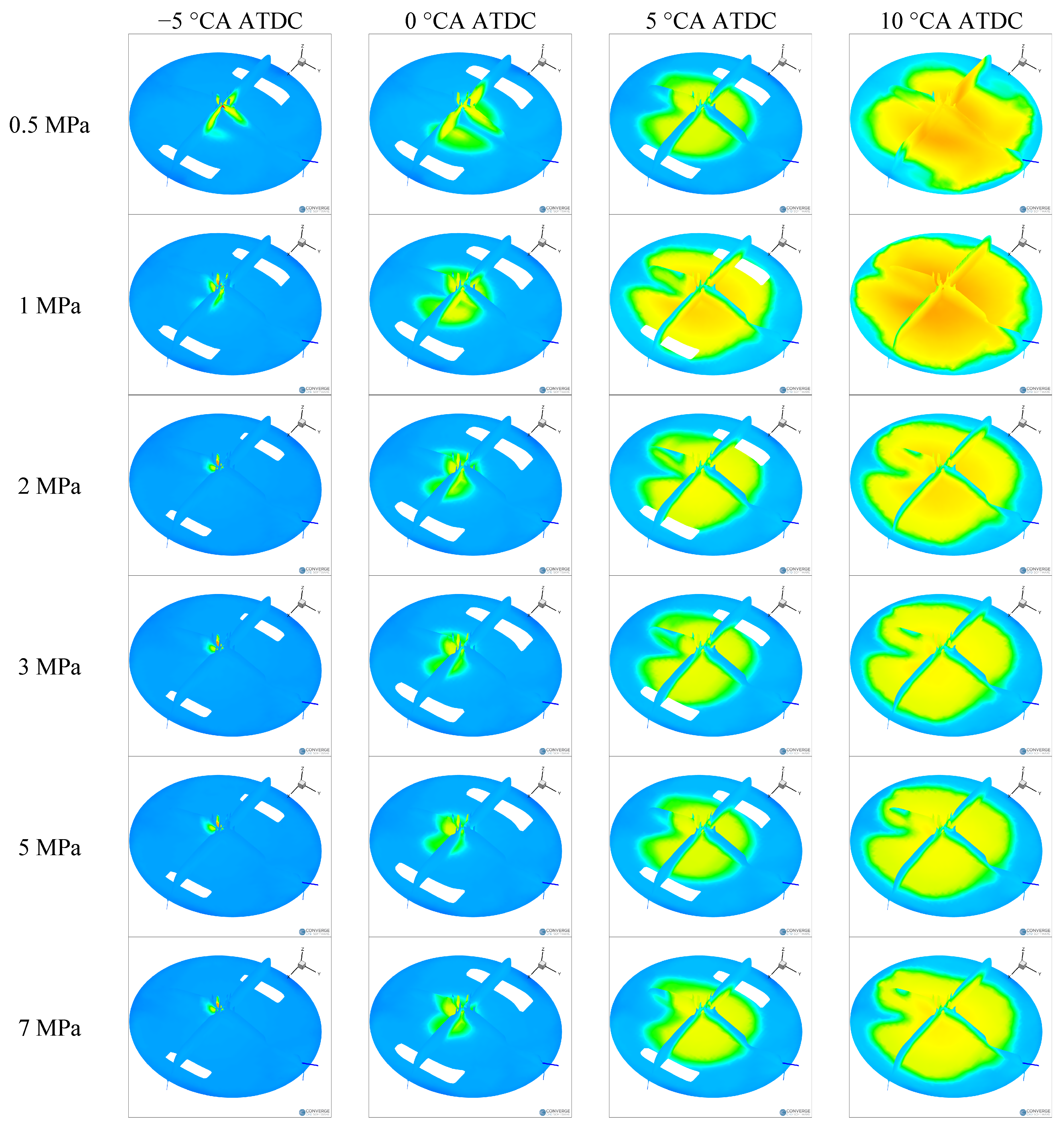
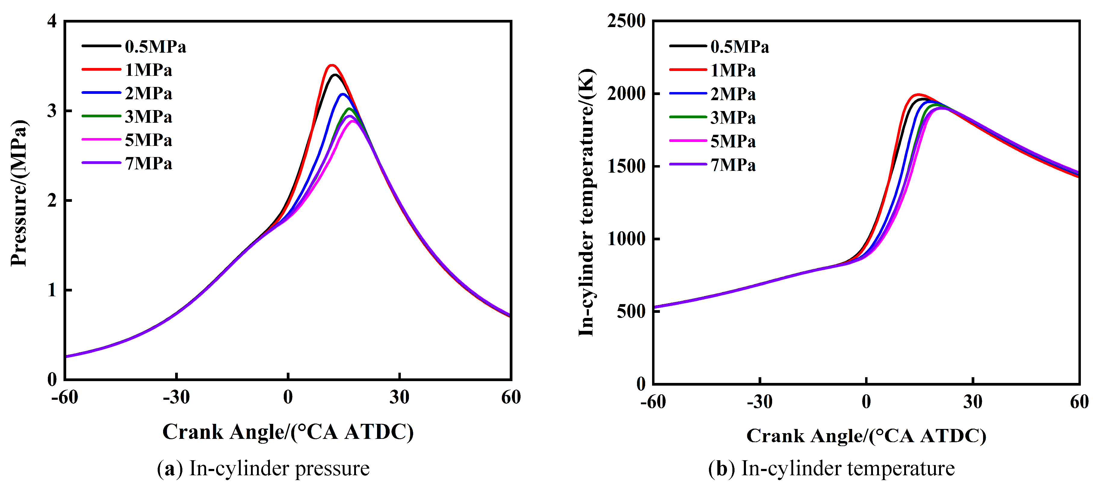
Figure 9a,b respectively shows the variation patterns of engine cylinder pressure and temperature under different cracking gas injection pressures. As the injection pressure of the cracking gas increases, the peak cylinder pressure shows a trend of first increasing, then decreasing, and then increasing again, while the corresponding crankshaft angle also undergoes a process of first advancing, then delaying, and then advancing again. Similarly, as the injection pressure increases, the peak cylinder temperature also shows a pattern of first increasing, then decreasing, and then increasing again, corresponding to an earlier, later delayed, and later advanced crankshaft angle. When the cracking gas injection pressure is 1 MPa, the peak values of cylinder pressure and cylinder temperature reach their maximum values, and the corresponding crankshaft angle is also the most advanced. Specifically, when the injection pressure of the cracking gas is 1 MPa, compared with 0.5 MPa, 3 MPa, and 7 MPa, the peak pressure in the cylinder increases by 0.11 MPa, 0.49 MPa, and 0.62 MPa, respectively, and the corresponding crankshaft angles advance by 0.9 °CA, 4.4 °CA, and 5.2 °CA, respectively. At the same time, under the same conditions, the peak temperature in the cylinder increases by 31 K, 70 K, and 94 K, respectively, and the corresponding crankshaft angles advance by 1.3 °CA, 4.8 °CA, and 6.4 °CA, respectively, compared with the above three pressures. These experimental results are mutually verified with the cylinder distribution state of hydrogen in Figure 5, indicating that when the injection pressure is 1 MPa, the layered distribution of hydrogen in the x-axis direction has a better effect on lean burn performance.
3.2.3. Further Analysis of Injection Pressure Effects on Combustion and Emissions
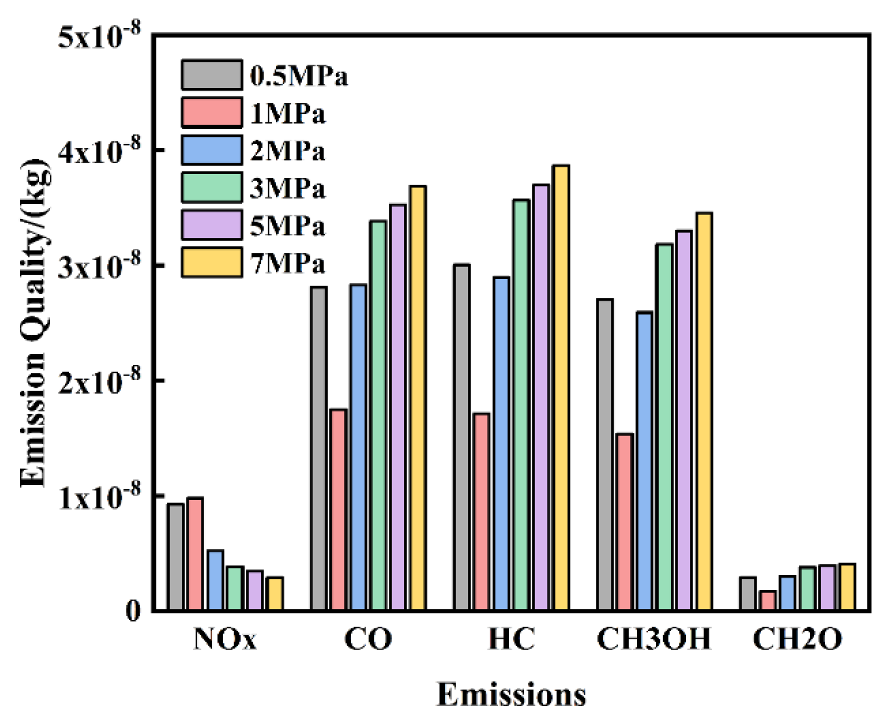
Figure 10 shows the variation of engine emission performance under different dissociated methanol gas injection pressures. The simulation results show that as the injection pressure of the cracking gas increases, NOx emissions first increase and then decrease; However, the emissions of CO, HC, CH3OH, and CH2O showed the opposite trend. It is worth noting that when the injection pressure of the cracking gas reaches 1 MPa, the NOx emissions reach their peak, while the emissions of CO, HC, CH3OH, and CH2O decrease to their lowest levels. This phenomenon can be explained by the changes in combustion speed and temperature in the cylinder. As the injection pressure increases, the combustion speed and temperature in the cylinder first increase and then decrease.
4. Conclusions
This study investigated the effect of DMG injection pressure on the dilution combustion performance of methanol inlet injection engines through simulation. Draw the following conclusions.
(1) When the injection pressure is 3 MPa, as the ambient pressure increases, the resistance to the dissociated methanol gas jet increases, and the jet shape becomes more concentrated. When the time is 0.9 ms, the ambient pressure increases from 0.1 MPa to 0.3 MPs. At 0.5 MPa and 0.7 MPa, the jet penetration distance is shortened by 18.9 mm and 37.4 mm, respectively.
(2) When the injection pressure exceeds 1 MPa, the hydrogen stratification in the cylinder mainly unfolds along the y-axis; On the contrary, when the injection pressure is 0.5 MPa and 1 MPa, hydrogen stratification unfolds along the x-axis. As the injection pressure of the dissociated methanol gas increases, the peak cylinder pressure first increases, then decreases, and then increases again. When the dissociated methanol gas injection pressure is 1 MPa, both the cylinder pressure and cylinder temperature peak reach their maximum values.
(3) When the DMG direct injection pressure is 1 MPa, compared with other injection pressure conditions, the in-cylinder peak pressure and peak temperature are increased by up to 0.62 MPa and 94 K, respectively, and CA50 is advanced by up to 5.2 °CA. NOx emissions reach their peak value (4.2 g/kWh), while the emissions of CO, HC, CH3OH, and CH2O are all minimized, with reductions ranging from 10% to 18%. This indicates that 1 MPa is a favorable injection pressure that balances combustion efficiency and unburned emissions.
Author Contributions
.X.M.: Conceptualization, Methodology, Investigation, Formal Analysis, Data Curation, Visualization, Writing—Original Draft Preparation; F.X.: Investigation, Data Curation, Validation, Visualization; J.D.: Software, Validation, Formal Analysis; M.L.: Resources, Supervision, Validation; C.Z.: Investigation, Resources, Data Curation; X.W.: Methodology, Writing—Review and Editing, Supervision; Z.J.: Conceptualization, Supervision, Project Administration, Funding Acquisition, Writing—Review and Editing. All authors have read and agreed to the published version of the manuscript.
Funding
This work was financially supported by the National Natural Science Foundation of China General Project (52476117); Changchun Science and Technology Development Plan Project (23Gzz20); Major Science and Technology Projects of Jilin Province and Changchun City (20240301004ZD).
Institutional Review Board Statement
Not applicable.
Informed Consent Statement
Not applicable.
Data Availability Statement
The original contributions presented in this study are included in the article. Further inquiries can be directed to the corresponding author.
Conflicts of Interest
The authors declare no conflict of interest.
Use of AI and AI-Assisted Technologies
No AI tools were utilized for this paper.
References
- 1.
Liu, R.; Cui, Q.; Li, H.; Wang, H.; Chen, X.; Jin, J.; Liu, J. Evaluating the Influence of the Compression Ratio on the Combustion Process Using Methanol, Gasoline, and Methanol-Gasoline Blends. Energy Rep. 2025, 14, 1645–1660. https://doi.org/10.1016/j.egyr.2025.08.003.
- 2.
Zhang, M.; Cao, J. Effects of Two-Stage Injection on Combustion and Particulate Emissions of a Direct Injection Spark-Ignition Engine Fueled with Methanol—Gasoline Blends. Energies 2025, 18, 415.
- 3.
Agus, D.; Adika, A.; Kurniawan, A. Results in Engineering Performance, Emissions, and Combustion Analysis of Gasoline-Ethanol-Methanol Blends in a Spark-Ignition Engine. Results Eng. 2025, 26, 105264. https://doi.org/10.1016/j.rineng.2025.105264.
- 4.
Wang, X.; Liu, Y.; Han, L.; Gong, Y.; Xie, F.; Su, Y. The Influence of Exhaust Gas Recirculation Coupling with Fuel Injection Pressure on the Combustion and Emission Characteristics of Engine Fueled with Methanol-Gasoline Blends. Fuel Process. Technol. 2024, 255, 108048. https://doi.org/10.1016/j.fuproc.2024.108048.
- 5.
Meng, X.; Xie, F.; Liu, Y.; Lai, K.; Jiang, X.; Jiang, B. Effect of Dilution Strategies on the Performance and Knocking in a Spark Induced Compression Ignition (SICI) Engine for Isopropanol-Butanol-Ethanol (IBE) Blends. Energy 2025, 319, 134941. https://doi.org/10.1016/j.energy.2025.134941.
- 6.
Zhao, H.; Qu, H.; Han, L.; Gong, Y.; Zhang, L.; Li, L. Effect of the Miller Cycle Strategy on Methanol and Ethanol Engines under Stoichiometric Combustion and Lean Burn. Energy 2025, 327, 136416. https://doi.org/10.1016/j.energy.2025.136416.
- 7.
Zhang, M.; Cao, J. Comparative Study on Combustion and Emission Characteristics of Methanol / Gasoline Blend Fueled DISI Engine under Different Stratified Lean Burn Modes. Fuel Process. Technol. 2024, 266, 108160. https://doi.org/10.1016/j.fuproc.2024.108160.
- 8.
Meng, X.; Xie, F.; Li, X.; Han, L.; Duan, J.; Gong, Y. Study on the Effects of Intake Valve Timing and Lift on the Combustion and Emission Performance of Ethanol, N-Butanol, and Gasoline Engine under Stoichiometric Combustion and Lean Burn Conditions. Energy 2024, 300, 131385. https://doi.org/10.1016/j.energy.2024.131385.
- 9.
Chen, G.; Kong, W.; Xu, Y.; Shen, Y.; Wei, F. Thermal Efficiency and Emissions Improvement of the Lean Burn High Compression Ratio HPDI NG Engine at Different Combustion Modes. Appl. Therm. Eng. 2024, 247, 123061. https://doi.org/10.1016/j.applthermaleng.2024.123061.
- 10.
Gong, C.; Li, Z.; Sun, J.; Liu, F. Evaluation on Combustion and Lean-Burn Limit of a Medium Compression Ratio Hydrogen / Methanol Dual-Injection Spark-Ignition Engine under Methanol Late-Injection. Appl. Energy 2020, 277, 115622. https://doi.org/10.1016/j.apenergy.2020.115622.
- 11.
Gong, C.; Li, Z.; Li, D.; Liu, J.; Si, X.; Yu, J.; Huang, W.; Liu, F.; Han, Y. Numerical Investigation of Hydrogen Addition Effects on Methanol-Air Mixtures Combustion in Premixed Laminar Fl Ames under Lean Burn Conditions. Renew. Energy 2018, 127, 56–63. https://doi.org/10.1016/j.renene.2018.04.047.
- 12.
Gong, C.; Li, Z.; Chen, Y.; Liu, J.; Liu, F.; Han, Y. In Fl Uence of Ignition Timing on Combustion and Emissions of a Spark-Ignition Methanol Engine with Added Hydrogen under Lean-Burn Conditions. Fuel 2019, 235, 227–238. https://doi.org/10.1016/j.fuel.2018.07.097.
- 13.
Ji, C.; Yang, J.; Liu, X.; Zhang, B.; Wang, S. ScienceDirect A Quasi-Dimensional Model for Combustion Performance Prediction of an SI Hydrogen-Enriched Methanol Engine. Int. J. Hydrogen Energy 2016, 41, 17676–17686. https://doi.org/10.1016/j.ijhydene.2016.07.146.
- 14.
Wang, H.; Zhao, Y.; Dong, X.; Yang, J. ScienceDirect Thermodynamic Analysis of Low-Temperature and Processes Cooled by Mixed-Refrigerants. Int. J. Hydrogen Energy 2022, 47, 28932–28944. https://doi.org/10.1016/j.ijhydene.2022.06.193.
- 15.
Li, B.; Zhong, F.; Wang, R.; Jiang, Y.; Chen, Y. Experimental and Numerical Study on a SI Engine Fueled with Gasohol and Dissociated Methanol Gas Blends at Lean Conditions. Energy 2024, 292, 130540. https://doi.org/10.1016/j.energy.2024.130540.
- 16.
Jiang, Y.; Chen, Y.; Xie, M. Effects of Blending Dissociated Methanol Gas with the Fuel in Gasoline Engine. Energy 2022, 247, 123494. https://doi.org/10.1016/j.energy.2022.123494.
- 17.
Chen, S. C.; Kao, Y. L.; Yeh, G. T.; Rei, M. H. ScienceDirect An Onboard Hydrogen Generator for Hydrogen Enhanced Combustion with Internal Combustion Engine. Int. J. Hydrogen Energy 2017, 42, 21334–21342. https://doi.org/10.1016/j.ijhydene.2017.03.013.

This work is licensed under a Creative Commons Attribution 4.0 International License.
 Suite 4002 Level 4, 447 Collins Street, Melbourne, Victoria 3000, Australia
 General Inquiries: info@sciltp.com