A structure-equipment coupling response analysis method is developed for synchronous lifting of large flexible structures, in which structural deformation, lifting-point load distribution, and hydraulic equipment response interact with each other. The flexible structure, hydraulic lifting equipment, and lifting-point interface are considered as an integrated system, and the bidirectional interaction between the structure and equipment is described through the transfer relationship among lifting-point displacement, velocity, and force. Based on this coupling mechanism, an AMESim (Siemens, Plano, TX, USA, v2021.1)-Simulink (The MathWorks, Natick, MA, USA, R2024b) co-simulation model is established to analyze the coupling response under basic loading and eccentric loading conditions. Lifting-point displacement and lifting force are selected as the main measured response indices, while displacement difference and lifting-force difference are used for quantitative comparison. The results show that the responses of different lifting points are generally consistent under basic loading, while structural flexibility still causes lifting-force redistribution. Under eccentric loading, the loaded-side lifting points carry larger lifting forces, and both the displacement difference and lifting-force difference become more pronounced. A scaled hydraulic synchronous lifting test platform (custom-built, Shanghai, China) is further used for validation. In the experiment, lifting-point displacement and lifting force are measured. The maximum lifting-point displacement difference increases from approximately 7.3 mm under basic loading to 10.1 mm under eccentric loading, and the maximum lifting-force difference increases from approximately 1030 N to 4000 N. These results indicate that eccentric loading strengthens the interaction between structural displacement response and lifting-force redistribution. The experimental results are generally consistent with the simulation results in overall trends, demonstrating that the proposed method can reflect the main coupling response characteristics during synchronous lifting. This study provides a reference for lifting-force analysis, equipment coordination, and construction parameter optimization.
- Open Access
- Article
Co-Simulation-Based Analysis and Experimental Validation of Structure-Equipment Coupling Response in Synchronous Lifting
- Yongming Bian 1,
- Keyuan Fan 1,
- Li Chen 2,*
Author Information
Received: 14 May 2026 | Revised: 01 Jun 2026 | Accepted: 04 Jun 2026 | Published: 24 Jun 2026
Abstract
Keywords
synchronous lifting | structure-equipment coupling | co-simulation | eccentric loading | experimental validation
1. Introduction
Large-span steel structures, spatial trusses, roof systems, bridge segments, and other large flexible components are increasingly used in modern construction projects. During integral assembly and final positioning, these structures are often lifted as a whole by multi-point hydraulic synchronous lifting systems. Compared with conventional single-point or single-machine lifting methods, multi-point synchronous lifting can reduce high-altitude assembly work and improve construction efficiency. However, large flexible structures usually have large spans, uneven stiffness distributions, and temporary boundary conditions during construction. As a result, the displacement response, structural deformation, and lifting-point force state may vary significantly during the lifting process. Previous studies have investigated construction-stage deformation, stress redistribution, and monitoring-based safety evaluation during integral lifting and jacking processes [1,2,3,4]. These studies provide useful references for construction simulation and safety assessment of large structural components.
On the equipment side, hydraulic synchronous lifting systems have also received considerable attention. The synchronization accuracy of multiple hydraulic cylinders is easily affected by load variation, valve nonlinearities, parameter uncertainty, oil compressibility, and external disturbances [5,6]. To improve multi-cylinder synchronization performance, different control methods have been proposed, including cross-coupling control, sliding mode control, model predictive control, neural-network-based control, and reinforcement-learning-based control [7,8,9,10]. These methods improve the displacement tracking and coordination ability of hydraulic lifting systems to different degrees. In addition, some recent studies have considered multi-cylinder coordinated coupling and synchronous load control under asymmetric or heavy-load conditions [11,12]. Nevertheless, most equipment-side studies mainly focus on actuator synchronization accuracy, while the deformation of the lifted flexible structure and the redistribution of lifting force among different lifting points are not fully considered.
For large flexible structures, structural deformation is closely related to the lifting-point constraints and load transfer paths. Flexible structure dynamics and rigid-flexible coupling methods provide theoretical support for describing structural deformation, modal response, and dynamic interaction in complex mechanical systems [13,14]. In lifting construction, the lifting points act as the direct connection interfaces between the hydraulic equipment and the flexible structure. Their layout, stiffness, and load state may significantly affect structural displacement, local deformation, and lifting-force distribution [15,16,17]. Therefore, the lifting point should not be regarded only as a geometric support position, but also as an interface for force and displacement transmission between the structure and the equipment.
In practical synchronous lifting, the flexible structure and hydraulic lifting equipment do not work independently. The hydraulic cylinders provide displacement and force input to the structure through lifting points, while structural deformation changes the load distribution at these lifting points and further affects the output response of the hydraulic equipment. This process forms a bidirectional interaction between structural deformation and equipment response. Existing rigid-flexible coupling and flexible multibody dynamics studies have provided effective modeling methods for systems involving large deformation, elastic vibration, and overall motion [18,19,20]. However, in the field of synchronous lifting construction, the bidirectional coupling relationship among lifting-point displacement, velocity, and force has not been sufficiently studied. In many existing analyses, the hydraulic lifting equipment is simplified as an ideal displacement boundary or an external force input, while the feedback effect of structural deformation on the equipment-side response is ignored. This simplification may lead to an incomplete understanding of displacement coordination and lifting-force redistribution, especially under eccentric loading.
To address this issue, this study develops a co-simulation-based structure-equipment coupling response analysis method for synchronous lifting. The flexible structure, hydraulic lifting equipment, and lifting-point interface are taken as the main research objects. The bidirectional interaction between the structure and equipment is described through the transfer relationship among lifting-point displacement, velocity, and force. A co-simulation model is established by combining the hydraulic lifting system model and the structural coupling calculation model. Basic loading and eccentric loading conditions are designed to analyze the influence of load distribution on lifting-point displacement, displacement difference, lifting force, and lifting-force difference. Finally, a scaled hydraulic synchronous lifting test platform is used for experimental validation, and the simulation and experimental results are compared in terms of overall variation trends. The objective of this study is to provide a reference for lifting-force analysis, equipment coordination, and construction parameter optimization in multi-point hydraulic synchronous lifting.
2. Materials and Methods
2.1. Structure-Equipment Coupling Mechanism in Synchronous Lifting
During synchronous lifting, the flexible structure and the hydraulic lifting equipment are connected through multiple lifting points. The hydraulic cylinders provide displacement input and lifting force to the structure, while the deformation of the flexible structure changes the reaction force and load distribution at the lifting points. Therefore, the structure and the equipment do not work independently. Instead, they form a coupled system through the lifting-point interfaces, where displacement, velocity, and force are transferred between the two subsystems.
As shown in Figure 1, the hydraulic lifting equipment acts on the flexible structure through the lifting points. From the equipment side, the output displacement and velocity of each hydraulic cylinder are transmitted to the corresponding lifting point. These motion inputs determine the local displacement response of the structure. From the structural side, the flexible deformation of the lifted structure changes the reaction force at each lifting point. The reaction forces are then fed back to the hydraulic cylinders as load variations, further affecting the equipment-side response.
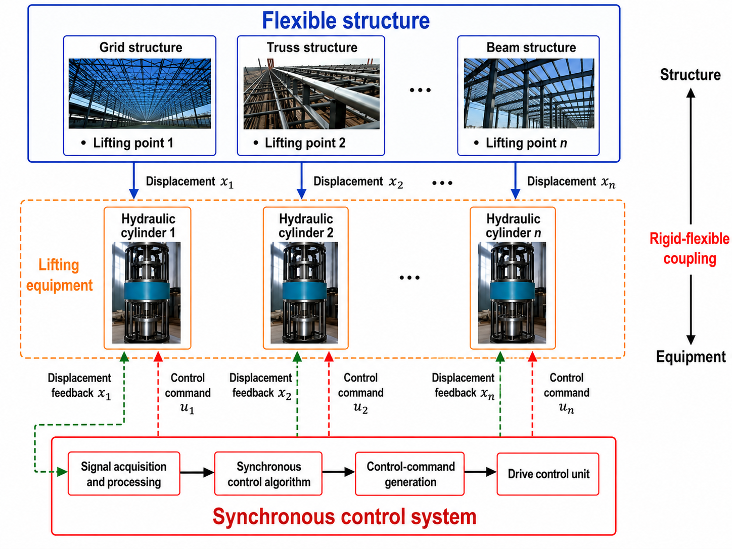
For a large flexible structure, the response of each lifting point is not only related to the corresponding hydraulic cylinder, but also affected by the deformation compatibility of the whole structure. When the displacement or load of one lifting point changes, the influence can be transmitted to other lifting points through the structural stiffness. As a result, the lifting forces are redistributed among different lifting points. This indicates that the lifting point is not merely a support or loading position, but a coupling interface between the structure and the equipment.
Under the basic loading condition, the external load is relatively balanced, and the displacement trends of different lifting points are usually close to each other. However, due to structural flexibility and lifting-point interaction, slight force redistribution may still occur. Under the eccentric loading condition, local load imbalance changes the structural force transfer path. The lifting points near the loaded region bear larger forces, while the forces at other lifting points decrease relatively. Consequently, the displacement difference and lifting-force difference among lifting points become more obvious.
Based on this mechanism, the structure-equipment coupling response in synchronous lifting can be regarded as a bidirectional feedback process. The hydraulic lifting equipment affects the structural response through cylinder displacement and lifting force, while the flexible structure feeds back to the equipment through lifting-point deformation and reaction force. This coupling mechanism provides the basis for the lifting-point response calculation and the AMESim-Simulink co-simulation model established in the following sections.
2.2. Mathematical Description of Lifting-Point Coupling Response
To quantitatively describe the interaction among multiple lifting points, the displacement and velocity deviations of each lifting point from the average motion state are used as the coupling response inputs. Suppose that the synchronous lifting system contains lifting points. The displacement and velocity of the lifting point at time are denoted as and , respectively. The average displacement and average velocity of all lifting points can be expressed as follows:
The displacement deviation and velocity deviation of the lifting point are defined as follows:
For all lifting points, the displacement deviation vector and velocity deviation vector can be written as follows:
Based on the equivalent structural stiffness and damping relationship at the lifting-point interfaces, the coupling force vector can be calculated as:
The lifting force at each lifting point can be expressed as the sum of the external lifting load and the coupling force component:
To evaluate the motion coordination of the synchronous lifting system, the maximum lifting-point displacement difference is introduced as:
A smaller indicates better displacement coordination among lifting points. Conversely, a larger value indicates a greater motion difference and a more obvious coordination deviation.
Similarly, the maximum lifting-force difference is used to evaluate the load distribution imbalance among lifting points:
Therefore, the lifting-point displacement difference and lifting-force difference are selected as the main evaluation indices in this study. The displacement difference reflects the motion coordination of the multi-point lifting system, while the lifting-force difference reflects the load redistribution among lifting points. Based on these indices, the coupling response characteristics under basic loading and eccentric loading conditions can be further analyzed.
2.3. AMESim-Simulink Co-Simulation Model
Based on the structure-equipment coupling mechanism described above, an AMESim-Simulink co-simulation model is established to analyze the coupling response of the synchronous lifting system. The co-simulation model consists of a hydraulic lifting system model, a synchronous control model, and a structural coupling calculation model. The hydraulic lifting system model is established in AMESim, while the synchronous control model and the structural coupling calculation model are established in Simulink. Through data exchange between AMESim and Simulink, the hydraulic execution process and the structural coupling calculation process are connected to form a bidirectional feedback framework.
The co-simulation framework is shown in Figure 2. The target displacement was first input into the synchronous control model in Simulink. According to the displacement tracking error of each lifting point, the control model generated the corresponding command signal and transmitted it to the hydraulic system model in AMESim. The hydraulic model then calculated the dynamic response of the lifting cylinders under the combined action of the control command and external load. During the lifting process, the cylinder displacement and velocity were exported from AMESim and used as the input variables of the structural coupling calculation module in Simulink.
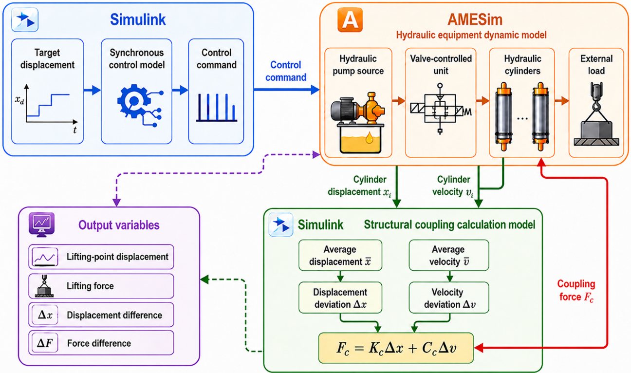
In the structural coupling calculation module, the average displacement and average velocity of the four lifting points were calculated first. Then, the displacement deviation and velocity deviation of each lifting point were obtained according to Equations (1)–(6). Based on these deviation variables, the coupling force was calculated using the equivalent stiffness and damping relationship expressed in Equation (7). The calculated coupling force was then fed back to the hydraulic model in AMESim and applied to the corresponding cylinder load side. In this way, the influence of structural deformation on the equipment-side load response could be considered.
Through this data exchange process, the hydraulic lifting equipment and the flexible structure were connected into a closed-loop coupling system. On the one hand, the hydraulic cylinders affected the structural response through displacement input and lifting force. On the other hand, the flexible deformation of the structure changed the lifting-point force distribution and fed back to the hydraulic cylinders as load variation. Therefore, the proposed co-simulation model can describe the main bidirectional interaction characteristics between the structure and the equipment during synchronous lifting.
In this study, the same co-simulation framework was used for both the basic loading condition and the eccentric loading condition. The basic loading condition was used to represent the relatively balanced lifting state, while the eccentric loading condition was used to simulate local load imbalance near selected lifting points. Under the two conditions, the target displacement, control parameters, and simulation settings were kept consistent. Therefore, the influence of load distribution on displacement coordination and lifting-force redistribution could be compared.
The main output variables of the co-simulation model included cylinder displacement, lifting-point displacement, lifting force, maximum displacement difference, and maximum lifting-force difference. Among them, cylinder displacement reflected the execution response of the hydraulic equipment, lifting-point displacement reflected the structural motion response, and lifting force reflected the load redistribution among different lifting points. The maximum displacement difference and maximum lifting-force difference were used as the main evaluation metrics for comparing the coupling response under different loading conditions.
To avoid excessive dependence on detailed component parameters, this study focused on the response characteristics and variation trends of the structure-equipment coupling system. The simulation results were mainly used to reveal the influence of load distribution on displacement difference and lifting-force difference. The effectiveness of the co-simulation analysis was further examined by comparison with the scaled synchronous lifting experiment.
2.4. Loading Conditions and Experimental Setup
To analyze the influence of load distribution on the structure-equipment coupling response, two loading conditions were designed in this study: basic loading and eccentric loading. The basic loading condition was used to represent the normal synchronous lifting process, in which the loads at the four lifting points were approximately balanced. The eccentric loading condition was used to simulate local load imbalance by applying an additional load near selected lifting points. Under the two loading conditions, the same lifting target and control parameters were adopted, so that the influence of load distribution on the coupling response could be compared.
In this study, lifting-point displacement and lifting force were selected as the main experimental response indices. Lifting-point displacement was used to describe the motion response of the structural lifting points, while lifting force was used to describe the load distribution and force redistribution among different lifting points. The loading conditions and response indices used in this study are summarized in Table 1.
Loading conditions and response indices used in this study.
| Category | Item | Description |
|---|---|---|
| Loading condition | Basic loading | The loads at the four lifting points are approximately balanced, representing the normal synchronous lifting condition. |
| Loading condition | Eccentric loading | An additional local load is applied near selected lifting points to simulate load imbalance during synchronous lifting. |
| Response index | Lifting-point displacement | Vertical displacement of the structural lifting points, reflecting the structural motion response. |
| Response index | Lifting force | Force at each lifting point obtained from strain-based conversion, reflecting load redistribution among lifting points. |
In the numerical example, a four-point synchronous lifting system was considered. The target lifting displacement was set to approximately 200 mm. Two loading conditions were analyzed: basic loading and eccentric loading. Under basic loading, the loads at the four lifting points were approximately balanced. Under eccentric loading, an additional local load was applied near selected lifting points to simulate load imbalance. The same lifting target and control parameters were used in both conditions, so that the influence of load distribution on lifting-point displacement and lifting force could be compared.
A scaled hydraulic synchronous lifting test platform was used to validate the proposed structure-equipment coupling response analysis method. The experimental platform mainly consisted of a load-bearing structure, four hydraulic lifting points, a hydraulic power unit, a synchronous control system, and a data acquisition system. The four hydraulic cylinders acted on different positions of the structure to simulate the multi-point synchronous lifting process. The hydraulic power unit provided the driving force for the cylinders, the synchronous control system coordinated the motion of each lifting point, and the data acquisition system recorded the lifting-point displacement and force responses during the experiment. The test platform is shown in Figure 3.
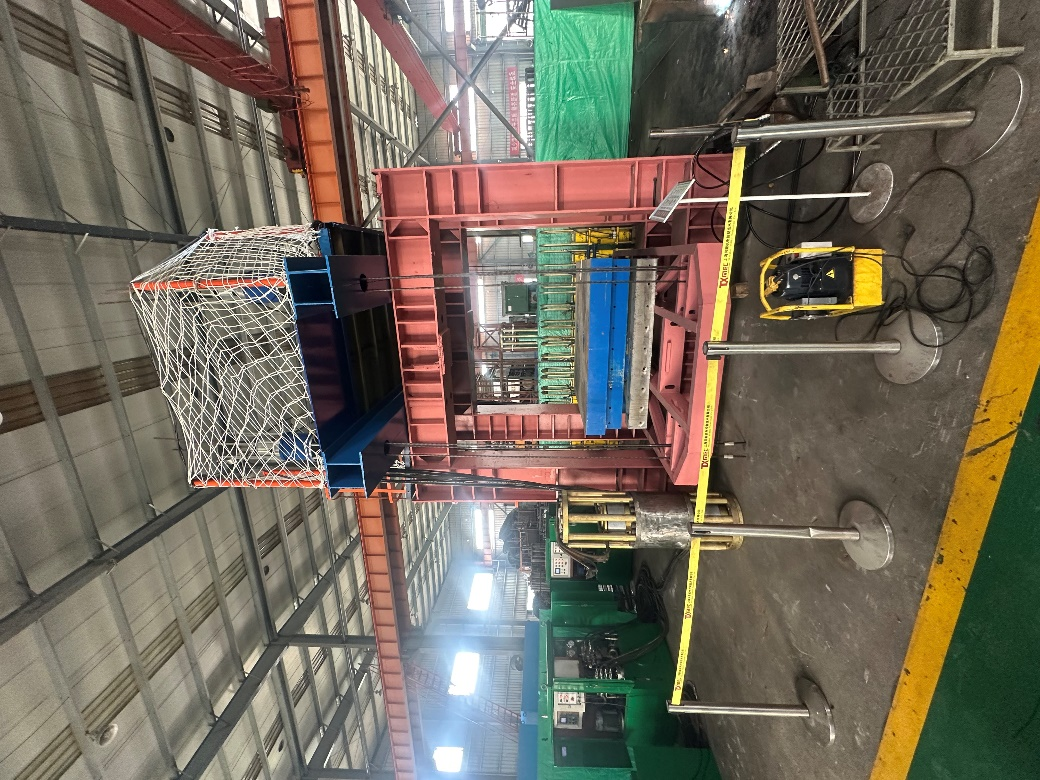
During the experiment, lifting-point displacement and lifting force were measured. The lifting-point displacement was collected by displacement sensors arranged near the structural lifting points. Strain gauges were arranged near the lifting-point regions to measure local structural strain, and the measured strain was converted into lifting force according to the calibration relationship between strain and force. Through these measurements, the coupling response was analyzed from two aspects: structural displacement response and lifting-point force redistribution.
The basic loading and eccentric loading tests were conducted under the same lifting target and control parameters. Under basic loading, the response consistency among different lifting points was mainly observed. Under eccentric loading, the changes in lifting-point displacement and lifting force were emphasized to evaluate the influence of local load imbalance on the coupling response. Since the scaled experimental platform differed from the co-simulation model in structural size, connection stiffness, boundary conditions, hydraulic fluctuation, and installation error, strict numerical equivalence was not adopted in this study. Instead, the comparison focused on the overall variation trends of lifting-point displacement and lifting force. This validation strategy was used to examine whether the proposed method could reflect the main structure-equipment coupling characteristics during synchronous lifting.
3. Results
3.1. Coupling Response Under Basic Loading
Under the basic loading condition, the loads at different lifting points are relatively balanced, and the synchronous lifting system mainly operates under normal coordinated lifting conditions. In this section, the lifting-point displacement response, displacement difference, lifting-force response, and lifting-force difference are analyzed to evaluate the structure-equipment coupling characteristics under balanced loading.
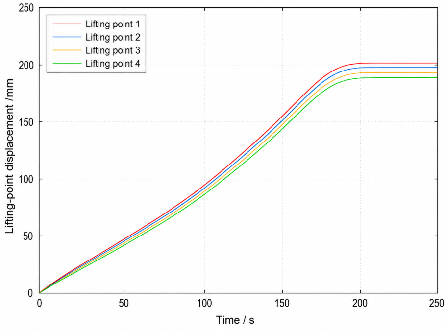
Figure 4 shows the lifting-point displacement response under the basic loading condition. The displacement curves of the four lifting points exhibit similar variation trends during the lifting process, indicating that the hydraulic synchronous lifting system can maintain good displacement coordination under balanced loading. The displacement of each lifting point increases with time and follows the lifting trajectory without obvious divergence. This result shows that the equipment-side synchronous control can effectively coordinate the motion of different lifting points when the external load distribution is relatively uniform.
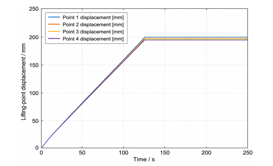
Although the displacement responses of different lifting points are generally consistent, small differences can still be observed among the four curves. These differences are mainly caused by the flexible deformation of the lifted structure and the interaction among lifting points. Since the lifting points are connected through the flexible structure, the displacement variation at one lifting point can be transmitted to other positions through the structural stiffness. Therefore, even under basic loading, the lifting-point displacement responses are not completely identical.
Figure 5 presents the lifting-force response under the basic loading condition. Compared with the displacement response, the lifting-force response shows more pronounced differences among different lifting points. The lifting forces fluctuate around the average load level, but the force at each lifting point is not completely the same. This indicates that displacement coordination does not necessarily mean uniform lifting-force distribution.
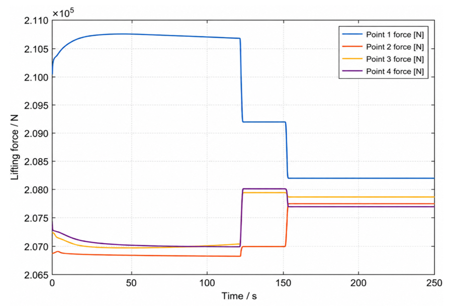
The difference in lifting force is mainly related to structural flexibility and load redistribution. During synchronous lifting, the deformation of the flexible structure changes the load transfer path among lifting points. As a result, some lifting points bear slightly larger forces, while others carry relatively smaller forces. This phenomenon demonstrates that the structure and the hydraulic lifting equipment interact with each other through the lifting-point interfaces.
Overall, under the basic loading condition, the synchronous lifting system exhibits good displacement coordination, and no obvious displacement divergence occurs among the lifting points. However, the lifting-force response still shows slight redistribution due to structural flexibility. Therefore, for the structure-equipment coupling analysis of synchronous lifting, both displacement response and lifting-force response should be considered. The basic loading condition mainly reflects the normal coordinated response of the system, while the force redistribution provides evidence of the coupling effect between the flexible structure and the hydraulic lifting equipment.
3.2. Coupling Response Under Eccentric Loading
Under the eccentric loading condition, an additional local load is applied near selected lifting points to simulate load imbalance during synchronous lifting. Compared with the basic loading condition, this condition can better reflect the influence of uneven load distribution on lifting-point displacement coordination and lifting-force redistribution.
Figure 6 shows the lifting-point displacement response under the eccentric loading condition. Compared with the basic loading condition, the displacement curves of different lifting points show more obvious differences during the lifting process. Although the four lifting points still move along the same general lifting direction, the displacement responses are no longer as consistent as those under balanced loading. This indicates that eccentric loading weakens the motion coordination of the multi-point synchronous lifting system.
The increase in displacement difference is mainly caused by the change in the structural force-transfer path. When local load imbalance occurs, the deformation of the flexible structure becomes uneven, and the lifting points near the eccentric load region are more strongly affected. Since the lifting points are connected through the flexible structure, the local deformation caused by the eccentric load is transmitted to other lifting points, resulting in larger displacement deviation among different lifting points. Therefore, the eccentric loading condition amplifies the displacement response difference caused by structural flexibility.
Figure 7 presents the lifting-force response under the eccentric loading condition. Compared with the basic loading condition, the differentiation of lifting forces among different lifting points becomes more significant. The lifting points close to the loaded region bear larger forces, while the forces of the non-loaded-side lifting points decrease relatively. This shows that eccentric loading does not simply increase the force at one lifting point, but changes the overall load distribution of the flexible structure.
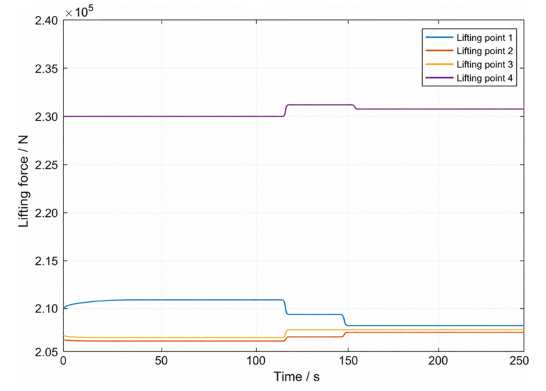
The lifting-force redistribution further affects the hydraulic lifting equipment through the lifting-point interfaces. When the force of one lifting point increases, the load state of the corresponding hydraulic cylinder changes, and this change may further influence the motion response of the equipment side. Therefore, the lifting-force difference under eccentric loading reflects the bidirectional interaction between the flexible structure and the hydraulic lifting equipment more clearly than that under the basic loading condition.
Overall, the eccentric loading condition leads to larger displacement differences and more pronounced lifting-force redistribution among lifting points. This indicates that load imbalance can amplify the structure-equipment coupling response during synchronous lifting. Compared with the basic loading condition, the coupling effect under eccentric loading is more significant, and both displacement coordination and force balance should be considered in the analysis of multi-point hydraulic synchronous lifting systems.
3.3. Experimental Validation of Coupling Response
To further verify the applicability of the proposed structure-equipment coupling response analysis method, experimental tests were conducted using the scaled hydraulic synchronous lifting platform described in Section 2.4. The measured lifting-point displacement and lifting force under basic loading and eccentric loading were compared with the simulation results in terms of overall variation trends.
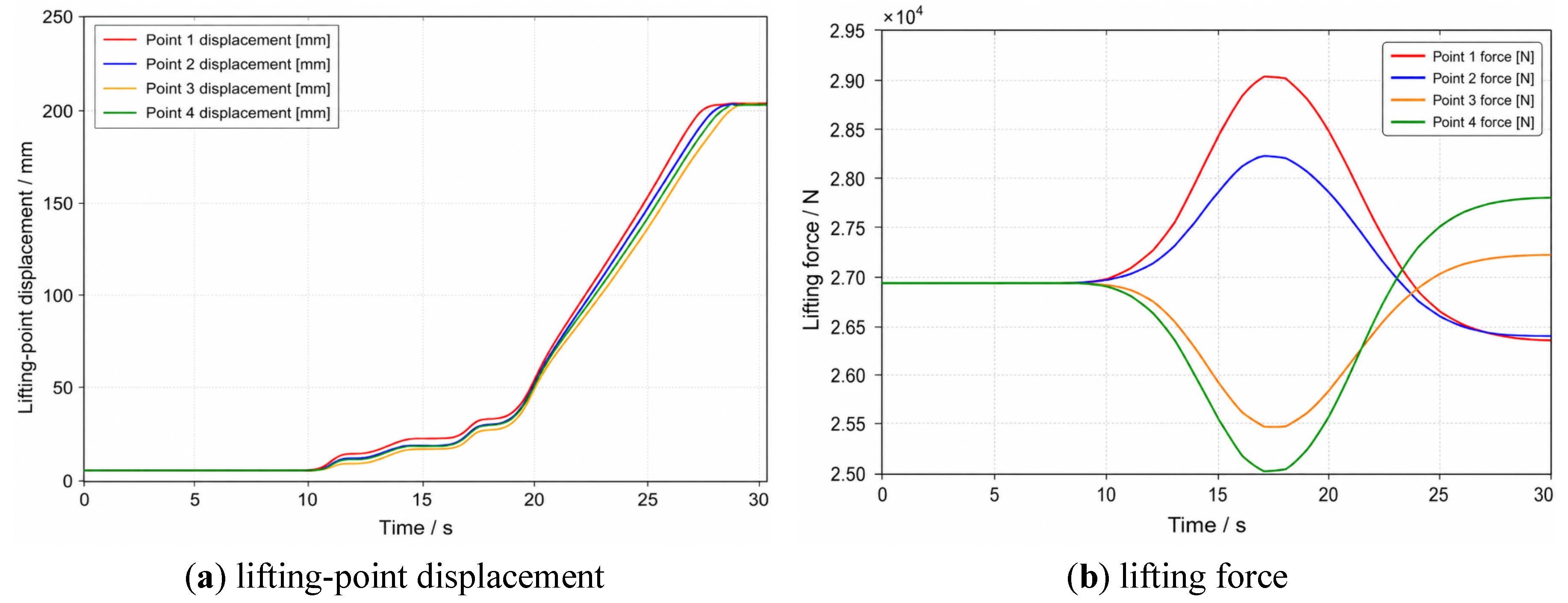
Figure 8 shows the experimental response under the basic loading condition. As shown in Figure 8a, the displacement curves of different lifting points exhibit similar variation trends during the lifting process. The displacement difference among lifting points remains relatively small, indicating that the experimental system can maintain good motion coordination under balanced loading. This trend is consistent with the simulation results under basic loading, where the four lifting points also show similar displacement responses. In the basic loading test, the maximum lifting-point displacement difference was approximately 7.3 mm, indicating that the experimental system maintained relatively good displacement coordination under balanced loading.
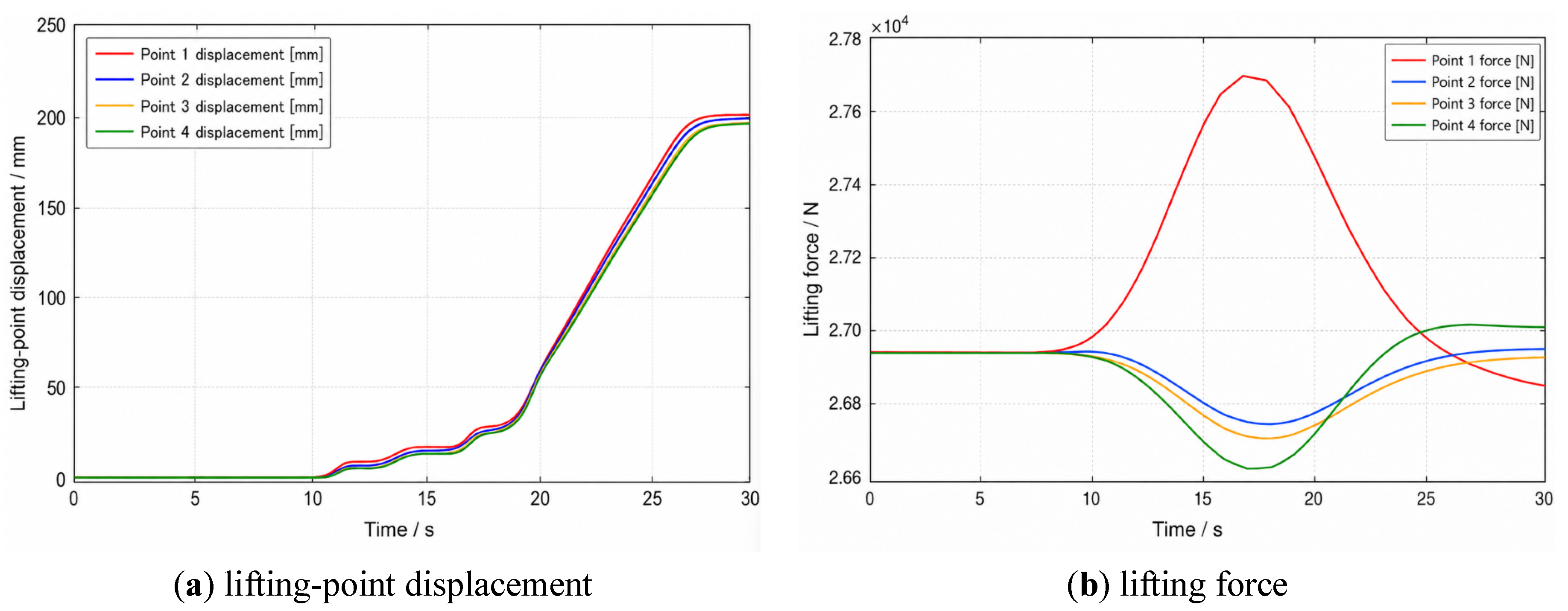
Figure 8b presents the experimental lifting-force response under the basic loading condition. The lifting forces of different points fluctuate around the average load level, but slight differences can still be observed among the four lifting points. This phenomenon is similar to the simulation result shown in Figure 5, indicating that structural flexibility can still cause lifting-force redistribution even when the external load is relatively balanced. Therefore, the experimental results confirm that displacement coordination does not necessarily mean completely uniform force distribution. The maximum lifting-force difference under the basic loading test was approximately 1030 N, showing that slight load redistribution still existed among different lifting points even when the displacement responses were relatively consistent.
Figure 9 shows the experimental response under the eccentric loading condition. Compared with the basic loading condition, the displacement difference among lifting points becomes more significant, as shown in Figure 9a. The lifting points near the loaded region show larger response deviations, while the other lifting points remain relatively close in trend. This result is consistent with the simulation results under eccentric loading. In the eccentric loading test, the maximum lifting-point displacement difference increased to approximately 10.1 mm. Compared with the basic loading test, this increase indicates that local load imbalance weakened the displacement coordination among lifting points.
As shown in Figure 9b, the lifting-force differentiation among different lifting points becomes more significant under eccentric loading. The loaded-side lifting points bear larger forces, while the non-loaded-side lifting points carry relatively smaller forces. This trend agrees with the simulation result shown in Figure 7. It indicates that eccentric loading changes the structural load transfer path and causes more pronounced lifting-force redistribution. Compared with the basic loading condition, the structure-equipment coupling response is further amplified under eccentric loading. The maximum lifting-force difference reached approximately 4000 N under eccentric loading, which was significantly higher than that under basic loading. This further confirms that eccentric loading amplifies the load redistribution among lifting points.
Overall, the experimental results show the same main variation trends as the co-simulation results. Under basic loading, the displacement responses of different lifting points are close to each other, and only slight force redistribution occurs. Under eccentric loading, both the lifting-point displacement difference and lifting-force difference increase, and the force redistribution among lifting points becomes more significant. Although numerical differences exist between simulation and experiment because of scaling effects, connection stiffness, boundary conditions, installation errors, and measurement uncertainty, the experimental results verify that the proposed method can reflect the main coupling response characteristics of the synchronous lifting system.
3.4. Quantitative Comparison of Coupling Response
Based on the simulation and experimental results, the structure-equipment coupling response showed different characteristics under basic loading and eccentric loading conditions. Under the basic loading condition, the load distribution among lifting points was relatively balanced. The displacement curves of different lifting points were close to each other, indicating that the synchronous lifting system had good motion coordination. However, the lifting-force response still showed slight differences among the lifting points, which indicated that structural flexibility could cause lifting-force redistribution even under balanced loading.
Under the eccentric loading condition, the coupling response became more significant. The additional local load changed the structural force-transfer path and increased the response difference among lifting points. As a result, the lifting-point displacement difference increased, and the lifting-force redistribution became more pronounced. The lifting points near the loaded region bore larger forces, while the non-loaded-side lifting points carried relatively smaller forces.
To further compare the simulation and experimental results, the relative error between the simulated and measured responses was calculated. Since lifting-point displacement and lifting force were measured in the experiment, the comparison focused on the maximum lifting-point displacement difference and the maximum lifting-force difference. The relative error was calculated as follows:
As shown in Table 2, the simulation and experimental results showed the same main variation trend. Compared with the basic loading condition, eccentric loading led to larger lifting-point displacement difference and lifting-force difference. This indicates that local load imbalance weakened the displacement coordination among lifting points and increased lifting-force redistribution. Although numerical deviations existed between simulation and experiment because of structural scale difference, connection stiffness, boundary conditions, installation error, and measurement uncertainty, the comparison results showed that the co-simulation model could reflect the main variation characteristics of the experimental response.
Error comparison between simulation and experiment under different loading conditions.
| Loading Condition | Response Index | Simulation Value | Experimental Value | Relative Error |
|---|---|---|---|---|
| Basic loading | Maximum lifting-point displacement difference/mm | 6.8 | 7.3 | 7.35% |
| Basic loading | Maximum lifting-force difference/N | 1120 | 1030 | 8.04% |
| Eccentric loading | Maximum lifting-point displacement difference/mm | 9.4 | 10.1 | 7.45% |
| Eccentric loading | Maximum lifting-force difference/N | 3720 | 4000 | 7.53% |
Under basic loading, the lifting-point displacement difference and lifting-force difference remained relatively small, indicating that the system maintained good coordination when the load distribution was approximately balanced. Under eccentric loading, both indices increased, showing that local load imbalance amplified the structure-equipment coupling response. Therefore, the error comparison further verifies the applicability of the proposed co-simulation method for analyzing the coupling response of multi-point hydraulic synchronous lifting.
4. Discussion
The results show that the structure-equipment coupling response in synchronous lifting is closely related to structural flexibility, lifting-point interaction, and load distribution. Although good displacement coordination can be maintained under balanced loading, slight differences still appear in the lifting-force response. This indicates that displacement synchronization does not necessarily mean uniform lifting-force distribution. Even when the displacement difference is small, the flexible deformation of the lifted structure can change the internal load transfer path and cause lifting-force redistribution among different lifting points.
The eccentric loading condition further reveals the bidirectional interaction between the flexible structure and the hydraulic lifting equipment. The additional local load changes the structural deformation pattern and breaks the original force balance among lifting points. This effect is transmitted through the structural stiffness to other lifting points and then fed back to the hydraulic cylinders through the lifting-point interfaces. Therefore, eccentric loading does not only affect local structural deformation, but also influences the load state of the whole structure-equipment coupling system. This explains why the displacement difference and lifting-force difference become more pronounced under eccentric loading.
From an engineering perspective, the results suggest that both displacement coordination and lifting-force balance should be considered in the analysis and control of large flexible structures during synchronous lifting. If only displacement synchronization is used as the evaluation criterion, the lifting-force redistribution caused by structural flexibility may be ignored. For balanced loading conditions, the main concern is to maintain stable displacement coordination and avoid excessive local force fluctuation. For eccentric loading or local load imbalance, more attention should be paid to lifting-force redistribution and the increase in displacement difference. Therefore, the proposed method can provide a reference for lifting-point arrangement, equipment coordination, and construction parameter optimization.
It should be noted that the scaled experimental platform cannot fully reproduce the structural scale, boundary stiffness, and complex construction environment of a real large-span lifting project. Therefore, the present validation mainly focuses on the consistency of response trends rather than strict numerical agreement. Further studies should consider more complex load disturbances, time-varying boundary conditions, and full-scale engineering cases.
5. Conclusions
In this study, a co-simulation-based structure-equipment coupling response analysis method was developed for multi-point hydraulic synchronous lifting of large flexible structures. The bidirectional interaction between the flexible structure and hydraulic lifting equipment was described through the transfer relationship among lifting-point displacement, velocity, and force. Based on the AMESim-Simulink co-simulation framework, the coupling response characteristics under basic loading and eccentric loading conditions were analyzed. A scaled hydraulic synchronous lifting test platform was further used to validate the effectiveness of the proposed method. The main conclusions are as follows.
The hydraulic lifting equipment and the flexible structure form a bidirectional coupling system through the lifting-point interfaces. The equipment-side displacement output affects the structural lifting-point response, while structural deformation changes the lifting-point force distribution and further feeds back to the hydraulic cylinders. Therefore, the synchronous lifting process should be analyzed from both structural response and equipment response perspectives.
Under the basic loading condition, the displacement responses of different lifting points are generally consistent, indicating good motion coordination of the synchronous lifting system. However, slight differences still exist in the lifting-force response. This shows that displacement synchronization does not necessarily mean uniform force distribution, and structural flexibility can still cause load redistribution among lifting points.
Under the eccentric loading condition, the displacement difference and lifting-force difference among lifting points increase more obviously. The lifting points near the loaded region bear larger forces, while the non-loaded-side lifting points carry relatively smaller forces. This indicates that local load imbalance changes the structural force-transfer path and amplifies the structure-equipment coupling response.
The experimental results obtained from the scaled hydraulic synchronous lifting platform showed similar variation trends to the co-simulation results in terms of lifting-point displacement and lifting force. Although numerical differences existed because of structural scale, connection stiffness, boundary conditions, installation error, and measurement uncertainty, the overall consistency of the response trends verified that the proposed method can reflect the main coupling characteristics of synchronous lifting.
Overall, the proposed method provides a useful reference for lifting-force analysis, equipment coordination, and construction parameter optimization in multi-point hydraulic synchronous lifting. Future work will focus on more complex construction conditions, such as time-varying loads, wind disturbance, multi-stage lifting, and further optimization of lifting-point layout and equipment coordination strategies.
Author Contributions
Y.B.: conceptualization, methodology, supervision, project administration, funding acquisition; K.F.: software, validation, investigation, data curation, writing—original draft preparation, visualization, formal analysis; L.C.: resources, writing—reviewing and editing, supervision, formal analysis. All authors have read and agreed to the published version of the manuscript.
Funding
This research was funded by the National Key R&D Program of China, grant number 2023YFF0613200.
Institutional Review Board Statement
Not applicable.
Informed Consent Statement
Not applicable.
Data Availability Statement
The data presented in this study are available within this article.
Conflicts of Interest
The authors declare no conflict of interest.
Use of AI and AI-Assisted Technologies
No AI tools were utilized for this paper.
References
- 1.
Yang, Y.; Du, H.; Yao, G.; Ma, X.; Men, W. Time-varying mechanical analysis of long-span spatial steel structures integral lifting in construction based on building information model. Sustainability 2023, 15, 11256.
- 2.
Ruan, R.; Lai, M.; Jiang, C.; Wang, J.; Lin, Y. Integral lifting of steel structure corridor between two super high-rise buildings under wind load. Buildings 2023, 13, 2441.
- 3.
Chang, L.; Zeng, F.; Guo, H.; Zhang, Z.; Gao, T. Construction simulation and monitoring of the jacking steel truss and main column of a super high-rise building. Buildings 2024, 14, 617.
- 4.
Wang, B.; Qian, S.; Muhammad, S.; Xu, M.; Shao, Z.; Li, N.; Wu, E. Case study of PLC synchronous lifting technology in concrete column reinforcement: Design, construction, and monitoring. Buildings 2025, 15, 3003.
- 5.
Li, R.; Yuan, W.; Ding, X.; Xu, J.; Sun, Q.; Zhang, Y. Review of research and development of hydraulic synchronous control system. Processes 2023, 11, 981.
- 6.
Lyu, L.; Liang, X.; Guo, J. Synchronization control of a dual-cylinder lifting gantry of segment erector in shield tunneling machine under unbalance loads. Machines 2021, 9, 152.
- 7.
Sun, C.; Dong, X.; Li, J. Cross-coupled sliding mode synchronous control for a double lifting point hydraulic hoist. Sensors 2023, 23, 9387.
- 8.
Gao, B.; Zhang, W.; Zheng, L.; Zhao, H. Research on position synchronization control strategy of double hydraulic cylinders based on cross-coupling. J. Braz. Soc. Mech. Sci. Eng. 2024, 46, 550.
- 9.
Li, D.; Lu, K.; Cheng, Y.; Wu, H.; Handroos, H.; Yang, S.; Zhang, Y.; Pan, H. Nonlinear model predictive control-cross-coupling control with deep neural network feedforward for multi-hydraulic system synchronization control. ISA Trans. 2024, 150, 30–43.
- 10.
Zhang, L.; Wang, J. Synchronous control of multiple hydraulic cylinders in aerial building machine using improved deep reinforcement learning. Autom. Constr. 2025, 179, 106448.
- 11.
Xue, Y.; Wang, B.; Xu, J.; Sun, Q.; Zhang, P. Research on multi-cylinder coordinated coupling synchronous control strategy based on strain energy. Sci. Rep. 2025, 15, 44277.
- 12.
Wu, C.; Wu, T.; Zhao, L.; Li, W.; Zhang, Q.; Li, L.; Chen, Q. Research on synchronous load control of shield beam for 50,000 kN hydraulic support test bench. PLoS ONE 2025, 20, e0335435.
- 13.
Lei, B.; Lin, H.; Zhang, M.; et al. A computational framework for modeling the interaction between flexible multibody systems and non-spherical particles. Powder Technol. 2026, 471, 122104.
- 14.
Chen, T.; Shan, J.; Wen, H. Distributed passivity-based control for multiple flexible spacecraft with attitude-only measurements. Aerosp. Sci. Technol. 2019, 94, 105408.
- 15.
Zheng, J.; Ji, P.H.; Wei, H.Z. The mechanics analysis and research of multi-suspension-centers integral lifting technology for long-span steel roof. Appl. Mech. Mater. 2012, 170–173, 3130–3134.
- 16.
Jin, Y.C.; Wang, R.; Lu, Y.Z. Steel channel lifting using tubular gin pole-assisted, multi-point, high-position whole lifting technology. Appl. Mech. Mater. 2012, 170–173, 3125–3129.
- 17.
Zhang, Q.; Mei, B.; Yang, H.; Hu, X.; An, W.; Yue, Y.; Xu, Y.; Wang, Z. Stress measurement and analysis of tower crane structural parameters under lifting position, rope length and load. Buildings 2025, 15, 1137.
- 18.
Shabana, A.A.; Hussien, H.A.; Escalona, J.L. Application of the absolute nodal coordinate formulation to large rotation and large deformation problems. J. Mech. Des. 1998, 120, 188–195.
- 19.
Gerstmayr, J.; Sugiyama, H.; Mikkola, A. Review on the absolute nodal coordinate formulation for large deformation analysis of multibody systems. J. Comput. Nonlinear Dyn. 2013, 8, 031016.
- 20.
Liu, J.Y.; Hong, J.Z. Dynamic modeling and modal truncation approach for a high-speed rotating elastic beam. Arch. Appl. Mech. 2002, 72, 554–560.


This work is licensed under a Creative Commons Attribution 4.0 International License.
 Suite 4002 Level 4, 447 Collins Street, Melbourne, Victoria 3000, Australia
 General Inquiries: info@sciltp.com