
To address the safety and lightweight requirements for hydrogen storage systems in fuel cell vehicles, this study investigates the structural design and simulation optimization of Type IV hydrogen storage cylinders. Material selection for the inner liner and the fiber winding layer was conducted based on high-pressure hydrogen storage standards. The geodesic winding theory and the grid theory were applied to design the winding angle and number of layers for the aramid fiber-reinforced composite. A 3D model was created in SolidWorks, and finite element simulation was employed to analyze the stress-strain characteristics under various operational conditions. To mitigate excessive stress in the inner liner, a self-tightening force optimization method was introduced. The results demonstrate that after applying a 90 MPa self-tightening pressure, the maximum stress in the inner liner was reduced to 28.6 MPa—below the yield strength of HDPE (29.4 MPa). Consequently, the cylinder’s fatigue life increased from 32,000 cycles to 100,000 cycles. Under the 70 MPa working pressure, the maximum strain in the fiber layer was 0.76%, and under the 158 MPa burst pressure, it reached 1.72%, both values meeting the design requirements. This research provides theoretical support for the engineering application of Type IV hydrogen storage cylinders.
- Open Access
- Article
Design and Simulation Optimization of Type IV On-Board Hydrogen Storage Cylinders
- Ankang Gu,
- Guo Yang,
- Shukun Liu,
- Zhuo Zhang *
Author Information
Received: 15 May 2026 | Revised: 18 Jun 2026 | Accepted: 23 Jun 2026 | Published: 10 Sep 2026
Abstract
Keywords
type IV hydrogen storage cylinder | hydrogen fuel cell vehicle | fiber winding | finite element simulation | self-tightening force optimization
1. Introduction
Given the dual-carbon goals, hydrogen energy is a critical development direction in the transportation sector. The major bottleneck for the commercialization of hydrogen fuel cell vehicles is the onboard hydrogen storage system, the performance of which is fundamentally limited by the safety, lightweight design, and durability of hydrogen storage cylinders [1]. Type IV hydrogen storage cylinders, characterized by a polymer liner and a fiber-wound layer structure, offer advantages such as a lightweight design (more than 30% lighter than Type III cylinders) and excellent resistance to hydrogen embrittlement, making them the mainstream technology for 70 MPa high-pressure hydrogen storage [2].
Current research on Type IV cylinders focuses primarily on optimizing filament winding processes, mitigating stress concentrations, and enhancing fatigue life. Chen Ruxun et al. [3] applied netting-theory-based optimization to the fiber winding angle and demonstrated a significant reduction in stress in the dome region. Bendine et al. [4] noted that high density polyethylene has become the standard liner material for Type IV cylinders owing to its excellent resistance to hydrogen permeation and formability, while finite element analysis has confirmed that carbon fiber belt reinforcement can reduce dome stress by 29% [5,6]. In the field of reinforced fibers, with their high specific strength and impact resistance, complement carbon fibers are showing increasing application potential under the dynamic operating conditions of vehicles [7,8]. In structural design, the compatibility of fiber winding parameters is critical. Geodesic winding theory ensures fibers do not slip during the winding process, providing the foundation for angle optimization [9]. The grid theory achieves matching between the number of winding layers and stress distribution through mechanical equilibrium equations [10]. However, in actual operating conditions, gas cylinders must withstand hydrogen charging and discharging cycles (with pressure fluctuations ranging from 0 to 70 MPa) and extreme impact loads. Theoretical calculations alone cannot adequately account for complex mechanical behavior, making finite element simulation technology an essential tool for performance analysis [11,12]. To accurately simulate the interface interaction between the inner liner and the composite layer, as well as stress concentration zones and fatigue damage accumulation, finite element analysis was employed [13,14]. Parameter optimization of self-tightening treatment, an effective method for enhancing the fatigue life of gas cylinders, remains a research hotspot. By preloading the cylinder to induce plastic deformation in the liner, the self-tightening process enables the fiber layers to take up a portion of the working stress in advance, thereby reducing the stress amplitude in the liner under cyclic conditions [15,16]. Research indicates that excessively high self-tightening pressure may cause excessive deformation or even cracking of the inner liner, while excessively low pressure fails to achieve fatigue strengthening. The critical value must be determined through a combination of simulation and experimentation [17,18].
Although phase-wise progress has been made in Type IV bottle technology, challenges persist in engineering applications: insufficient bonding strength at the interface between the inner liner and fiber layer may lead to delamination failure [19], the impact of material performance degradation under extreme temperatures (−40 °C to 85 °C) on structural safety remains incompletely understood [15]. This paper systematically addresses material selection, structural design, simulation analysis, and self-tightening force optimization for 40 L Type IV cylinders, aiming to provide technical reference for the engineering of high-pressure hydrogen storage equipment.
2. Hydrogen Storage System Composition and Type IV Cylinder Structural Design
2.1. Components of A Vehicle Hydrogen Storage System
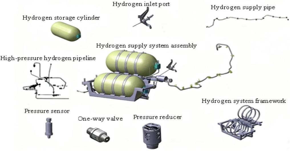
The composition of the on-board hydrogen storage system is shown in Figure 1: hydrogen storage cylinders equipped with cylinder valves, hydrogen supply lines, hydrogen filling ports, high-pressure hydrogen pipelines, pressure sensors, check valves, pressure regulators, and hydrogen system trusses. The hydrogen storage cylinders primarily store hydrogen, while cylinder valves control its inflow and outflow. The hydrogen supply pipe, filling port, and high-pressure hydrogen pipeline form the filling structure, primarily ensuring safety and compliance during hydrogen refueling. The internal pressure sensor monitors the pressure within the tank. The check valve prevents backflow of hydrogen into the storage tank. The pressure reducer lowers the pressure of hydrogen exiting the tank. The hydrogen system truss serves to mount the hydrogen storage tank [20]. The design section of this paper primarily focuses on hydrogen storage cylinders.
2.2. Type IV Hydrogen Storage Cylinder Structural Design
2.2.1. Material Selection
The structural design of Type IV hydrogen storage cylinders is highly coupled with material selection, where optimal material matching is central to ensuring their comprehensive performance. The cylinder comprises an inner liner, end caps, a fiber-wound layer, and an outer protective layer. Material selection for each component must balance performance requirements, cost control, and manufacturing feasibility.
The liner’s primary function is to provide hydrogen gas tightness, which requires the material to possess excellent hydrogen permeation resistance, mechanical properties, and process adaptability. High-density polyethylene (HDPE) was selected as the liner material due to its yield strength of 29.4 MPa and elastic modulus of 874 MPa satisfy the fundamental structural strength requirements. Additionally, HDPE exhibits outstanding hydrogen barrier properties and superior chemical stability, and it resists hydrogen embrittlement. From a manufacturing and lightweighting perspective, HDPE enables complex geometries through injection molding. Its low density contributes to reducing the overall cylinder mass, aligning with the weight reduction requirements of vehicle-mounted hydrogen storage systems [21].
As a critical end-of-tube structure, the end cap must ensure both structural integrity and reliable sealing. The selection of aluminum alloy 6061-T6 leverages its high strength and excellent ductility to withstand high-pressure hydrogen loads. Its superior corrosion resistance and material compatibility facilitate sealed connections with the inner liner and winding layer, balancing mechanical properties with assembly processability.
The winding layer is the primary load-bearing structure for the cylinder’s pressure resistance and therefore requires high strength, high modulus, and fatigue resistance. An aramid fiber/epoxy composite material (65% fiber volume fraction) is employed: Aramid fibers exhibit tensile strengths up to 3500 MPa with a density of only 1.44 g/cm³, enabling lightweight construction while maintaining strength. The epoxy matrix, with its superior adhesion and chemical stability, firmly bonds the fiber bundles into an integrated load-bearing structure that collaboratively resists internal pressure loads [22].
The outer protective layer must withstand damage to the winding layer caused by ultraviolet radiation, mechanical impact, and chemical corrosion. A 2 mm-thick glass fiber/polyester resin composite material is selected: glass fiber provides UV aging resistance and mechanical protection, while polyester resin confers excellent corrosion resistance and formability to the composite, jointly forming a reliable outer protective system.
The material selection for Type IV hydrogen storage cylinders establishes a functional system: “HDPE liner for leak sealing—aluminum alloy end caps for strong connections—aramid winding for load-bearing—fiberglass composite layer for environmental resistance.” This approach meets the mechanical and safety requirements for high-pressure hydrogen storage while achieving lightweight design through low-density materials, balancing performance, cost, and manufacturing feasibility.
2.2.2. Structural Parameter Design
The structural parameter design of Type IV hydrogen storage cylinders is the core process for balancing volumetric efficiency and strength performance. It requires integrating geodesic winding theory, mesh theory, and engineering application requirements to achieve quantitative parameter optimization.
I. Inner Tank Dimensions: Collaborative Design of Winding Path and Volume Requirements
The inner liner dimensions are determined based on geodesic winding theory to ensure optimal fiber winding paths and meet volumetric requirements. Through computational optimization, the cylinder diameter is set at 280 mm with a length of 518 mm. The end caps adopt an ellipsoidal structure with an ellipsoidal ratio m = √2 (short axis 99 mm), precisely controlling the total volume to 40 L. The advantages of this dimensional design are twofold: firstly, it provides a uniform winding surface for the fibers, preventing stress concentration caused by abrupt geometric changes; secondly, the curvature optimization of the ellipsoidal head enables the spiral-wound fibers to transition smoothly to the end, reducing the risk of wrinkling in the winding layers while meeting the design specifications for hydrogen storage capacity.
II. Fiber Winding Parameters: Precise Matching of Load Distribution and Structural Stability
The helical and circumferential hybrid winding scheme employs differentiated parameter design to achieve directional load-bearing:
(1) Helical winding: Focuses on axial load bearing. Its core parameter, the helix angle, is calculated based on the polar hole radius (50 mm) and cylinder body radius (140 mm) to be 19.65°. This angle, based on geodesic principles, ensures fibers neither slip nor cross during winding, achieving uniform coverage of the inner liner surface and guaranteeing effective axial force transmission.
(2) Circumferential Winding: Designed with a 90° circumferential angle to maximize fiber circumferential load-bearing capacity, directly counteracting circumferential stresses in high-pressure hydrogen environments.
III. Number of Winding Layers: Balancing Strength Assurance and Lightweight Design
To meet the requirements of 70 MPa working pressure and 158 MPa burst pressure, the design incorporates 33 spiral layers and 44 circumferential layers (single-layer thickness 0.35 mm), with a total thickness of 26.95 mm [23]. The advantage of the multi-layer structure lies in its ability to prevent localized overloading through a hierarchical stress gradient distribution. Simultaneously, by optimizing the ratio between the helical and circumferential layers (3:4), the overall stress distribution aligns with the fiber strength characteristics. This approach reduces material redundancy while meeting pressure resistance requirements, achieving dual objectives of weight reduction and cost control.
IV. Performance-Oriented Summary of the Parameter System
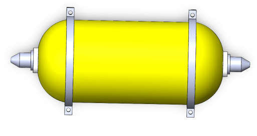
The aforementioned structural parameters establish an integrated design logic linking “dimensions-helix angle-layers”: the inner liner dimensions provide the fundamental geometry for the winding process, while the helix angle and circumferential angle enable targeted load distribution.The three-dimensional model of the hydrogen storage tank is shown in Figure 2. Layer design directly correlates with pressure resistance performance metrics. The synergistic interaction of these three elements ensures structural stability at 70 MPa operating pressure while accommodating both the 40 L capacity and lightweight requirements, providing quantifiable parameter support for the engineering application of Type IV hydrogen storage cylinders.
3. Finite Element Simulation
3.1. Introduction to Finite Element Analysis Software
In this section, the stress–strain behavior and fatigue life of the hydrogen storage cylinder structure were simulated using the SolidWorks Simulation. The modeling and analysis were conducted in strict accordance with the finite element analysis specifications for pressure vessels. A quarter-symmetric model was adopted, retaining the core structural features—the cylindrical body, the ellipsoidal heads, and the aluminum alloy bosses—while omitting non-critical details such as local fillets and assembly clearances, thereby reducing the computational cost without compromising accuracy. Material properties were assigned accordingly: the HDPE liner was modeled as an elastic–plastic material, the aramid fiber layer as an orthotropic elastic material, and the aluminum alloy bosses with their corresponding parameters. Bonded contact was defined at all component interfaces, fixed constraints were applied to the end faces of both bosses, and symmetric constraints were imposed on the symmetry planes. Second-order tetrahedral solid elements were employed, with mesh refinement applied to stress concentration regions such as the head transition zones and the boss areas; the mesh independence was verified to ensure solution accuracy. Subsequently, cyclic loading was introduced, and the fatigue life was calculated using the stress–life (S–N) method.
3.2. Grid Partitioning
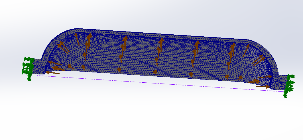
In engineering practice, mesh theory is primarily applied to calculation of fiber layer parameters for composite cylinders. By establishing circumferential and helical winding models for the cylinder body and heads, and incorporating the distribution of internal pressure loads, the radial and axial fiber stress ratios are separately determined to establish the winding angle and number of winding layers. While this method is convenient, it also has its limitations. First, theoretical fiber strength values do not accurately represent actual processing strength during winding. Real-world fabrication is influenced by multiple factors, making precision difficult to achieve. Second, design models overly idealize the process by neglecting matrix bonding, interlaminar shear, and humid thermal effects, overlooking numerous subtle factors. This makes it difficult to predict long-term steady-state performance. Mesh theory typically serves as an initial design tool and requires integration with finite element simulation and experimental validation to achieve an engineering closed-loop, ensuring a balance between structural safety and economic efficiency. Mesh theory provides a solution for the design of fiber-wound pressure vessel shells [24]. It should be noted that the grid analysis method is an idealized design approach, and its results are influenced by various factors. In actual production and design processes, it is necessary to consider the impact of these factors in practice and make timely corrections during both the design and machining stages. The inner liner is divided into a total of 13,152 grid cells, as shown in Figure 3 below.
3.3. Setting Constraints and Loads
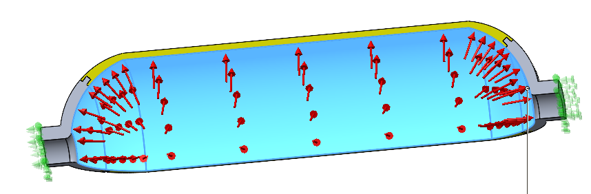
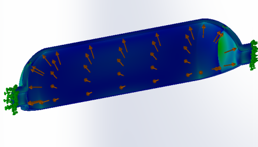
In this analysis, Figure 4 shows the quarter-section model of the cylinder. Symmetry constraints in the corresponding directions were applied to the two axial section planes of the cylinder to prevent undesired deformation. In addition, to restrict the degrees of freedom and eliminate indeterminate rigid-body motion, a fixed constraint (zero degrees of freedom) was imposed at the cylinder boss. To ensure simulation integrity, a rigid connection was assumed between the boss and the cylinder body during the constraint setup. The load was uniformly distributed and applied normal to the selected surfaces. A uniform internal pressure load acting normal to the wall was applied to the inner surface of the liner. Three typical load cases were defined: a working pressure of 70 MPa, a hydrostatic test pressure of 105 MPa, and a burst pressure of 158 MPa. For fatigue analysis, a cyclic internal pressure varying from 0 to 70 MPa was adopted. Bonded contacts were defined between the liner and the filament-wound layer, and between the liner and the aluminum alloy bosses, while interfacial slip and delamination failure were neglected.
3.4. Effect of Fiber Tension on Plastic Liners
During the fiber winding process, each layer of fiber applies radial pressure to the previously wound fiber layers due to the layered winding method. When winding the Nth layer, the tension in the fibers causes the Nth layer to exert uniform external pressure on the surface of the inner composite material. Calculation formula [25]:
FN is the fiber tension for the Nth layer; α is the winding angle for the Nth layer; RN−1 is the radius when wound up to the (N−1)th layer; b is the width of the fiber bundle.
Due to radial compressive stress in the fiber layers, the inner liner undergoes contraction. This causes the inner fiber layers to experience some relaxation, resulting in weakened confinement. Based on experimental experience, compressive stress generally stabilizes after the fourth winding layer. Therefore, during calculations, only the compressive stress generated by the tensile stress in the first four fiber layers is considered:
The fiber tension in this article is 40 N, it follows that the stress in the first four layers is 0.23 MPa.
3.5. Stress-Strain Analysis of the Inner Liner
First, a three-dimensional model of the liner was created in SolidWorks based on the pre-calculated dimensions. The inner material was defined as high-density polyethylene (HDPE) and the metal boss material as aluminum alloy 6061-T6. The connection between the boss and the liner was defined as a fully bonded contact, and fixed constraints were applied to the boss ends. Mesh generation was performed concurrently; higher-order elements were employed on the curved surfaces of the boss and the cylinder body to ensure accuracy. A total of 21,397 elements were generated. Stress analysis of the liner was then conducted, and the results are shown in Figure 5.
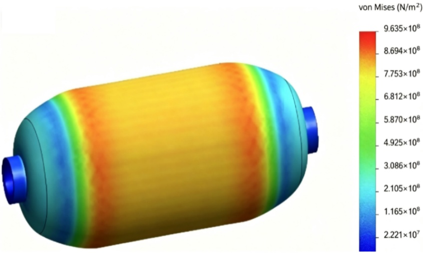
Figure 5 indicates that the maximum stress reaches 963.6 MPa, while the minimum stress is 22.21 MPa. The maximum stress significantly exceeds the yield strength of high-density polyethylene. Without self-tensioning constraints, the cylinder would become unusable. Subsequently, an analysis of the hydrogen storage cylinder’s strain was conducted, with the results shown in Figure 6.
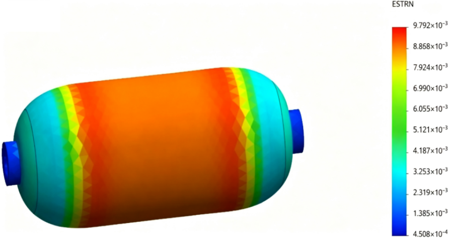
As shown in Figure 6, the maximum strain of 0.9792% does not exceed the 2% limit specified in the design standards for hydrogen cylinder liners. Since strains in mesh analysis are typically smaller than actual values, self-preload must be introduced to address stress concentration issues and excessive strain.
3.6. Actual Manufacturing Process for Fiber Reinforcement Layer of Gas Cylinders
The design of fiber-reinforced layers for gas cylinders requires an approach that integrates both theory and manufacturing practice. From a theoretical standpoint, the netting theory should be strictly followed to determine the preliminary winding parameters. The stress–strain contour plots obtained from finite element simulations can then be combined with practical fabrication experience to refine the design when manufacturing difficulties arise. In actual production, theoretical calculations must continuously guide design optimization. For example, determining the hoop and helical winding angles, as well as the exact number of fiber layers to be wound, necessitates theoretical calculations that are subsequently adjusted based on actual processing conditions.
3.7. Strain Analysis of the Fiber Layer
First, the 3D model of the fiber layer with pre-calculated data was created using SolidWorks. The material properties were defined as aramid, with end-fixed constraints applied during mesh generation. Mesh partitioning for the head and cylinder body was performed based on curvature to ensure dimensional accuracy, resulting in a total of 17,320 mesh elements. Fiber layers corresponding to the specified winding patterns were generated. Subsequently, strain analysis was performed on the fiber layers of the hydrogen storage cylinder under various operating conditions.
Figure 7 shows the strain distribution contour map of the fiber layer in a hydrogen storage cylinder under a working pressure of 70 MPa. The figure indicates that the maximum strain in the fiber layer occurs at the junction between the cylinder body and the end cap, while the maximum strain in the cylinder body direction occurs within the cylinder body section. This demonstrates significant deformation in these areas, with the maximum strain reaching approximately 0.7604%. As the requirement stipulates that strain should be less than 2%, the designed cylinder does not violate the regulations.
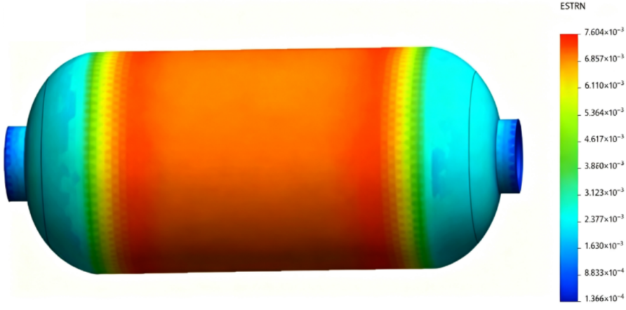
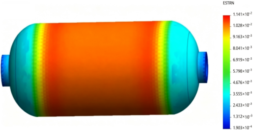
Figure 8 shows the strain distribution contour map of the fiber-wound layer at 105 MPa. The figure indicates that the maximum longitudinal strain in the fiber layer occurs at the transition between the cylinder section and the head. However, the maximum radial strain appears in the cylinder section, with a value of 1.141%, which is below the required 2%. Additionally, although the strain at the polar hole bend increases, it does not exceed the allowable strain for the fibers, confirming the design is reasonable.
The minimum burst pressure test was conducted at 158 MPa. As shown in Figure 9, the strain generated in the fiber layers of the hydrogen storage cylinder was primarily distributed across the cylinder body. The maximum strain reached 1.717%, which did not exceed the 2% allowable limit for the fibers. Therefore, this operating condition meets the requirements for hydrogen storage cylinders.
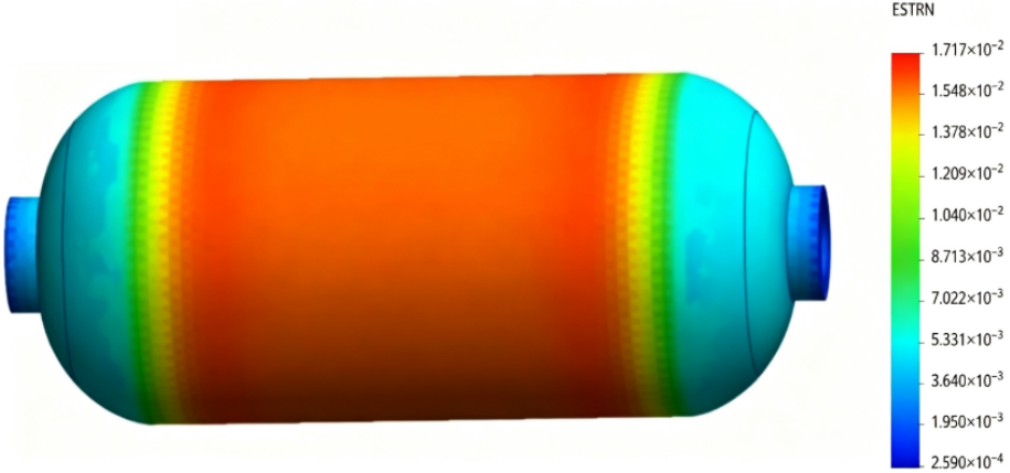
To validate the reliability of the numerical model, the fiber strain obtained under the 158 MPa burst condition was compared with published data for Type IV cylinders of the same specifications. The calculated value of 1.72% lies within the reasonable range of 1.5–1.9% reported in the literature, yielding a deviation of less than 6%. In addition, the failure regions are consistent with those observed in the literature, confirming that the modeling parameters are appropriately set. A quantitative comparison of the results under the three operating conditions reveals that the maximum strain in the fiber layer increases nearly linearly with the internal pressure. The strain increased by approximately 50% as the pressure rose from 70 MPa to 105 MPa, and by about 51% from 105 MPa to 158 MPa. No abrupt increase was observed over the entire pressure range, demonstrating good structural strength stability.
4. Implementation Plan for Optimizing Self-Tightening Force of Type IV Hydrogen Storage Cylinders
4.1. Material Parameters
The mechanical properties of high-density polyethylene plastic material can be retrieved from the built-in database in SolidWorks, as summarized in Table 1. The data can be directly imported into the material definition of the analysis software.
Mechanical parameters of high density polyethylene plastic materials.
| Design Item | Value | Unit |
|---|---|---|
| Elastic Modulus | 874 | MPa |
| Poisson’s Ratio | 0.38 | |
| Yield Strength | 29.4 | MPa |
4.2. Simulation Module Settings
(1) Material Settings
Table 2 lists the HDPE material property settings used in the self-tightening process simulation. These encompass the core mechanical and physical properties—including elastic constants, strength, and density—and serve as the constitutive basis for the elastoplastic deformation calculation of the liner, the stress distribution solution, and the fatigue life analysis. The parameter values are, on the whole, consistent with the nominal material properties presented in Table 2. In particular, the shear modulus was derived from the elastic modulus and Poisson’s ratio using the isotropic material relationship, thereby ensuring the mechanical self-consistency of the material model employed in the simulation.
Attribute Settings of Materials.
| Attribute | Numerical value | Unit |
|---|---|---|
| Elastic modulus | 84,000,000 | Newton/m2 |
| Poisson’s ratio | 0.38 | Not applicable |
| Shear modulus | 0 | Newton/m2 |
| Density of quality | 953 | kg/m3 |
| Tensile strength | 30,000,000 | Newton/m2 |
| Compressive strength | Newton/m2 | |
| Yield strength | 29,400,000 | Newton/m2 |
| Coefficient of thermal expansion | 1/k |
(2) Fixed Settings
When fixing hydrogen storage cylinders, the fixed end is positioned on the metal interface surface of the cylinder. Fixed constraints are employed to ensure stable head fixation during simulation, as shown in Figure 10.
4.3. Simulation Analysis of Fatigue Life for Gas Cylinder Structures
According to GB24160-2009 [26] Fiber-Wound Cylinders for Compressed Natural Gas for Vehicles, the fiber stress ratio must be greater than or equal to 2.75 ensure the high reliability of the composite winding layer under sustained and cyclic loading conditions. The same standard specifies that the self-tightening pressure must not exceed 109 MPa.
Fatigue life simulation was performed to assess the effect on the cylinder’s fatigue life. Based on SolidWorks simulation results, further optimization and refinement of the materials, structural parameters, and manufacturing processes can be carried out, thereby extending the cylinder’s service life and enhancing structural strength and safety.
In the simulation procedure, a static stress analysis was first selected in SolidWorks, and a 3D model was created. Materials were then defined: high-density polyethylene (HDPE) for the cylinder body, and the system’s default 6061-T6 aluminum alloy data for the bosses. Fixed constraints were applied at both ends of the bosses. A self-tightening pressure of 90 MPa was first applied to the liner, after which a cyclic internal pressure varying from 0 to 70 MPa was imposed for the fatigue analysis. The damage and life distribution maps obtained from the pre-optimization model are shown in Figure 11 and Figure 12
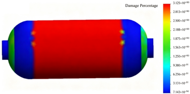
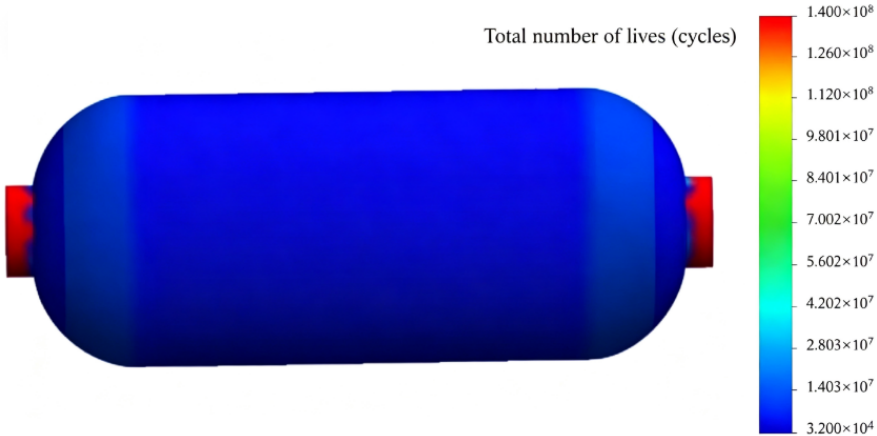
Figure 13 and Figure 14 indicate that the damage in the hydrogen storage cylinder was primarily concentrated on the cylinder body. Consistent with the overall stress distribution, the region with the lowest fatigue life was located at the area of maximum stress on the cylinder body, exhibiting a fatigue life of 32,000 cycles.
Subsequently, fatigue analysis optimization was conducted. The previously performed static stress analysis was imported into the load conditions, followed by the optimized fatigue analysis. For the autoclave simulation, the process requirements specified that the autoclave pressure must be maintained at 90 ± 0.5 MPa, with a pressure holding time of 28 ± 1 s. The simulation medium was required to be deionized water (20 ± 2 °C). The fiber stress ratio was set to 2.5.
The optimized results for damage and life were obtained.
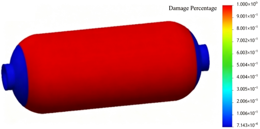
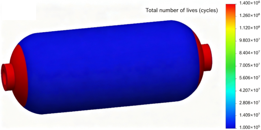
This diagram also shows that damage to the hydrogen storage cylinder is primarily concentrated in the shoulder region. The mitigation of stress concentration consequently reduces the damaged area, thus increasing the service life from 32,000 to 100,000 cycles—a substantial improvement.
Without the self-tightening treatment, the liner lacked residual compressive stress to buffer the working loads. During the hydrogen charging–discharging cycles (0–70 MPa), the liner was continuously subjected to high-amplitude tensile stress, with a maximum value of 963.6 MPa—far exceeding the yield strength of HDPE. This led to rapid fatigue crack initiation, resulting in an overall fatigue life of only 32,000 cycles. After the application of a 90 MPa self-tightening pressure, plastic deformation occurred in the liner, and the subsequent elastic recovery of the fiber composite layer induced stable residual compressive stress on the inner wall of the liner. Under cyclic loading, this residual compressive stress offset a large portion of the working tensile stress, thereby significantly reducing the alternating stress amplitude in the liner. The maximum stress was lowered to 28.6 MPa, which lies below the material’s yield strength of 29.4 MPa. This effectively delayed crack initiation and propagation, extending the fatigue life of the cylinder to 100,000 cycles—an increase of 212.5%.
5. Conclusions
This study focused on a 40 L Type IV on-board hydrogen storage cylinder, and the work encompassed material selection, structural design, and finite element simulation, with particular emphasis on the optimization of the self-tightening pressure. The structural scheme employing an HDPE liner combined with an aramid fiber winding layer proved capable of meeting the strength requirements for 70 MPa vehicle-mounted hydrogen storage. Under a working pressure of 70 MPa, the maximum strain in the composite layer was 0.76%, and at the burst pressure of 158 MPa it reached 1.72%, both values remaining below the allowable strain limit of 2%. After applying a self-tightening pressure of 90 MPa, the maximum stress in the liner was reduced to 28.6 MPa, which lies below the material yield strength of 29.4 MPa, thereby effectively suppressing the cumulative plastic damage in the liner. Consequently, the fatigue life of the cylinder was extended from 32,000 cycles to 100,000 cycles—an increase of 212.5%—confirming the significant life-enhancing effect of the self-tightening process on Type IV hydrogen storage cylinders.
This study was performed exclusively under room-temperature conditions and did not account for the influence of extreme temperatures (from −40 °C to 85 °C) on material properties and structural life. Future work will include coupled thermal–structural simulations and high- and low-temperature fatigue tests, with the goal of further refining the full-spectrum life assessment methodology for Type IV hydrogen storage cylinders.
Author Contributions
A.G.: software, methodology, writing—original draft preparation; G.Y.: data curation, validation; S.L.: investigation, writing—reviewing and editing; Z.Z.: conceptualization, supervision. All authors have read and agreed to the published version of the manuscript.
Funding
This research received no external funding.
Institutional Review Board Statement
Not applicable.
Informed Consent Statement
Not applicable.
Data Availability Statement
Not applicable.
Conflicts of Interest
The authors declare no conflict of interest exists in the submission of this manuscript.
Use of AI and AI-Assisted Technologies
During the preparation of this work, the authors used AI-assisted tools to assist language polishing. After using this tool/service, the authors revised and edited the content as needed and take full responsibility for the content of the published article.
References
- 1.
Yang, Q.; Fang, M.; Li, J.; Mao, Z.; Bao, H.; Ge, X.; Wan, X. Real fire testing and performance evaluation of fully loaded hydrogen storage systems for hydrogen fuel cell vehicles. Fuel 2025, 397, 135446.
- 2.
Garche, J.; Roth, C.; Smirnov, V. Type IV hydrogen storage tanks: Materials, design, and safety. J. Power Sources 2019, 427, 128–140.
- 3.
Chen, R.X.; Wang, Y.; Zhou, L. Application of grid theory in structural optimization of filament wound pressure vessels. Eng. Mech. 2022, 39, 234–241.
- 4.
Bendine, A.; Boutarbouch, M.; Bouiadjra, M. Finite element analysis of composite pressure vessel with dome reinforcement. Compos. Struct. 2020, 232, 111538.
- 5.
Mou, W.; He, G.; Zhou, C.; Gan, B.; Liu, Y.L.; Shi, S.S.; Xia, M.L. Molecular dynamics study on hydrogen permeation behavior and mechanism in polyethylene type IV hydrogen storage cylinder liner. J. Chem. Phys. 2025, 162, 234703.
- 6.
Kim, J.H.; Park, S.J.; Lee, J.K. Effect of hydrogen embrittlement on the mechanical properties of HDPE for type IV hydrogen storage tanks. Polym. Test. 2020, 85, 106415.
- 7.
Zhang, H.; Zhang, M.; Li, J.B.; Yang, B.; Abbas, S.C.; Fu, C.L.; Chen, T.; Xia, Y.Y.; Liu, J.W.; Du, X.Y.; et al. Aramid nanofiber-based functional composite materials: Preparations, applications and perspectives. Compos. Part B Eng. 2024, 271, 111151.
- 8.
Zhao, X.; Liu, Y.; Wang, Q. Comparative study on mechanical properties of carbon fiber and aramid fiber reinforced composites for hydrogen storage tanks. Compos. Struct. 2021, 267, 113812.
- 9.
Wang, X.; Chen, X.; Fan, Z.; Cao, W.H.; Li, J.Z.; Liu, G.H.; Wang, Q.Y.; Ma, Y.T.; Xie, P.C.; Yang, W.M. In situ temperature-controlled rotational molding for self-building ribs in PA6 liner for type IV hydrogen storage tanks. Polym. Eng. Sci. 2025, 65, 3005–3017.
- 10.
Wang, L.; Zhang, X.; Li, D. Optimal design of filament winding angle for type IV hydrogen storage tanks based on geodesic theory. Int. J. Mech. Sci. 2020, 179, 105602.
- 11.
Hu, H.; Li, S.; Wang, J.; Zu, L. Structural design and experimental investigation on filament wound toroidal pressure vessels. Compos. Struct. 2015, 121, 114–120.
- 12.
Chen, L.; Ouyang, M.; Li, J. Finite element analysis of type IV hydrogen storage tank under cyclic pressure. Int. J. Hydrog. Energy 2020, 45, 24067–24078.
- 13.
Yuan, K.; Liu, Z. A structural mechanics analysis on a Type IV hydrogen storage tank during refueling and discharging. Eng. Fail. Anal. 2024, 165, 108822.
- 14.
Liu, C.; Zhang, Y.; Wang, H. Finite element simulation of interface debonding in type IV hydrogen storage tanks. Compos. Interfaces 2021, 28, 412–428.
- 15.
Wu, X.; Yang, B.; Zhou, S. Strength and failure analysis of fiber-wound composite gas cylinder via numerical simulation. Materials 2024, 17, 717.
- 16.
Zhang, L.; Li, X.; Wang, Y. Optimization of autofrettage pressure for type IV hydrogen storage tanks. Thin-Walled Struct. 2021, 165, 107912.
- 17.
Zhang, G.; Zhu, H.Y.; Wang, Q.; Zhang, X.W.; Ren, M.F.; Xue, S.N.; Li, G. Buckling analysis of thin-walled metal liner of cylindrical composite overwrapped pressure vessels with depressions after autofrettage processing. Sci. Eng. Compos. Mater. 2021, 28, 540–554.
- 18.
Li, W.; Zhang, Y.; Chen, G. Numerical simulation of autofrettage process for type IV hydrogen storage tanks with HDPE liner. J. Press. Vessel Technol. 2020, 142, 061402.
- 19.
Li, C.; Qin, Z.; Li, Y.; Chen, Z.C.; Liu, J.L.; Liang, J.G.; Feng, J. Investigation on mechanical behaviors under fatigue load of stacking sequences considering autofrettage process for highly reliable hydrogen storage vessel. J. Energy Storage 2024, 82, 110538.
- 20.
Khan, S.; Kumar, A. Failure analysis in advance cylindrical composite pressure vessel under pressure & temperature for hydrogen storage: A comprehensive review. Polym. Compos. 2025, 46, 2933–2973.
- 21.
Aardahl, C.; Rassat, S. Overview of systems considerations for on-board chemical hydrogen storage. Int. J. Hydrog. Energy 2009, 34, 6676–6683.
- 22.
Dong, C.; Liu, Y.; Li, J.; Bin, G.F.; Zhou, C.L.; Han, W.L.; Li, X. Hydrogen permeability of polyamide 6 used as liner material for type IV on-board hydrogen storage cylinders. Polymers 2023, 15, 3715.
- 23.
Zhang, H.; Li, H.; Ashraf, M.; Ciorbi, O. Experimental Study and Theoretical Analysis of the Mechanical Properties of Aramid Fiber-Reinforced Polymer–Bamboo Composites. Int. J. Appl. Mech. 2025, 17, 2550038.
- 24.
Wang, T.Q.; Ge, P.H.; Gao, D.B.; Gao, G.; Qi, T. Winding pattern design for composite pressure vessels based on fiber overlap and stacking optimization. J. Compos. Mater. 2026, 60, 1199–1216.
- 25.
Zhou, Y.; Zou, Y.; Xia, Q.; Cao, L.K.; Zhang, M.H.; Shen, T.; Du, J.K. Simulation Analysis and Optimization Design of Dome Structure in Filament Wound Composite Shells. Polymers 2025, 17, 1421.
- 26.
GB 24160-2009; Fiber-Wound Cylinders for Compressed Natural Gas for Vehicles. China Standards Press: Beijing, China, 2009.

This work is licensed under a Creative Commons Attribution 4.0 International License.

 Suite 4002 Level 4, 447 Collins Street, Melbourne, Victoria 3000, Australia
 General Inquiries: info@sciltp.com