
Downloads
Download


This work is licensed under a Creative Commons Attribution 4.0 International License.
Review
A Review of Development of Natural Gas Engines
Lidong Liu 1, Mengli Zhang 1, and Zhengbai Liu 2, *
1 College of Automobile and Traffic Engineering, Liaoning University of Technology, Jinzhou 121001, China
2 School of Innovation and Entrepreneurship, Southern University of Science and Technology, Shenzhen 518055, China
* Correspondence: liuzb3@sustech.edu.cn
Received: 4 January 2023
Accepted: 22 February 2023
Published: 9 March 2023
Abstract: Natural gas has been successfully applied to the operation of internal combustion engines (ICEs) in various applications including automotive vehicles and generator sets, and is becoming a promising alternative fuel in ICEs due to its advantages such as the excellent knock resistance, stable combustion process, and low pollutant emissions. The operation cost of vehicles using natural gas engines (NGEs) is remarkably reduced, as the price of natural gas is over 50% lower than that of gasoline or diesel fuel. This review describes three stages of the NGEs development followed by discussions of natural gas resources, mechanisms underlying structural design and combustion process of NGEs, as well as different technologies applied in NGEs. The scientific guidance for research and development of NGEs is also provided in this review.
Keywords:
natural gas natural gas engine alternative fuel combustion1. Introduction
More and more attentions have been paid to the crisis of energy and climate change in the world. Stricter and stricter policies and regulations have been applied by governments of many countries due to over 20% pollutant emissions coming from automotive vehicles. Driven by the low cost, abundant resources, and desires to reduce the carbon emissions, it is expected that more natural gas would be put into application of automobiles in near future [ 1].
Natural gas vehicles (NGVs) were on the market in the 1930s, and their development has been lasted for near a hundred years. The technologies of NGVs are becoming mature, and easy to use after development in recent years [ 2]. The advanced electronic control and manufacturing methods have led to the high performance, safety, and reliability of NGVs. The driving distance of NGVs from 50–70 kilometers in early years has been increased to near a thousand kilometers today. The weight of natural gas tank and the size of filling station have been greatly reduced, and the network of filling stations has been gradually built up [ 3]. As a result, it is as convenient to fill NGVs as gasoline or diesel vehicles.
In this review, three stages of natural gas engines’ (NGEs) development are briefly described. The natural gas resources are outlined. The mechanisms underlying structural design and combustion performance of NGEs are examined. The technologies that can be applied to NGEs are discussed respectively. It is hoped that this review work can provide a good reference to scholars and engineers in automotive engineering field.
2. Engine Development and Resources of Natural Gas
There are two main factors on application of natural gas engines. One is the natural gas engine development, and the other one is the availability of natural gas resources [ 4– 6].
2.1. Natural Gas Engine Development Stages
At the present time, the third generation of NGEs has been put into mass production. As the time goes by, the development of NGEs [ 7] can be roughly divided into three stages or generations based on the natural gas intake methods. A mixer located in the intake pipe was used in the first generation of NGEs. In the second generation of NGEs, an approach of port natural gas injections was applied. The technology of direct cylinder natural gas injections is applied to the third generation of NGEs [ 8].
2.1.1. The First Generation of Natural Gas Engines (NGEs)
An intake pipe mixer was used in the first generation of NGEs. The air and natural gas were supplied to the mixer at the same time [ 9]. This approach of natural gas supply was simple, but the amount of natural gas admitted into the cylinder could not be controlled precisely. In general, there were three methods to control the concentration and flow rate of the air and natural gas mixture in the first generation of NGEs. (1) Under the condition that the flow passage cross section of natural gas remained constant, the mixture concentration was adjusted by controlling the natural gas inlet time. (2) Under the condition of constant natural gas inlet time, the mixture concentration was controlled by changing the area of cross section of natural gas flow passage. (3) The natural gas flow rate was controlled by adjusting the pressure of the natural gas supplied. The mixture flow rate was adjusted by an intake throttle valve in the intake pipe for the above mentioned three control methods. The mixture in the cylinder was ignited by the spark plug, followed by the flame propagation.
2.1.2. The Second Generation of NGEs
An approach of port natural gas injections was used in the second generation of NGEs. The port natural gas injector was near the intake valve located in the engine’s intake port or manifold [ 10]. Based on the engine operation requirements, the injector was manipulated by the engine electronic control unit (ECU), which could precisely control the amount of the natural gas injected at the constant injection pressure, followed by attainment of better combustible mixture than that in the first generation of NGEs. The air flow rate was adjusted by the intake throttle valve in the intake pipe. The ignition and combustion processes were similar to those in the first generation of NGEs. In addition, the technologies of exhaust gas recirculation (EGR) and Miller cycle could be used in the second generation of NGEs. The three-way catalysts (TWC) could be combined with the exhaust after treatment system (ATS) to reduce the engine pollutant emissions.
2.1.3. The Third Generation of NGEs
In the third generation of NGEs, the technology of direct cylinder natural gas injections was applied, which could precisely control the mixture concentration and flow rate [ 11]. The intake throttle valve in the intake pipe was removed. The natural gas was directly injected into the cylinder by using an electronically controlled injector and mixed with air to form combustible mixture. Based on the mixture distributions [ 12], different combustion mechanisms were formed, such as the diffusion combustion, stratified combustion, and homogeneous combustion. There were two basic approaches of mixture ignition [ 13]. One was that the mixture was ignited by the spark plug, followed by flame propagation. The other one used the dual fuel system, in which a small amount of diesel was injected into the cylinder. The diesel was compressed to ignition, and the mixture was ignited by the ignition flame. The technologies of EGR and Miller cycle could also be used in the third generation of NGEs. In addition, particulate traps and TWCs were used in the exhaust system to reduce the emissions of particulate and other harmful substances in the third-generation of NGEs.
2.2. Natural Gas Resources
Similar to crude oil and coal, natural gas is a fossil fuel stored in the Earth's crust. The natural gas is called the oil gas if accompanied with oil, the coal derived gas if related to coal, and the biogas or the organic hydrocarbons if broken down by organic bacteria. The composition of natural gas varies depending on the location of its resources.
2.2.1. Natural Gas Based on Fossil Fuels
An ICE is a power machine in which fuel is burned, and the heat energy generated by the combustion is converted into the mechanical energy. A gaseous fuel engine is an ICE that burns fossil gaseous fuels including the compressed natural gas (CNG), liquefied natural gas (LNG), and liquefied petroleum gas (LPG). Due to the increasing pressure of oil shortage and the global environmental pollution in recent years [ 14], people urgently hope to find the economic, clean, and safe fuels to replace petroleum fuels, which makes gaseous fuel enter a period of rapid development [ 15].
2.2.1.1. Compressed Natural Gas (CNG)
Simply speaking, NGEs are fueled by natural gas. The methane content of natural gas is generally above 90%, which makes it a good fuel for automobile engines. At present, natural gas is recognized worldwide as the most realistic and technically matured alternative fuel for gasoline and diesel fuels. At the same time, the popularized and applied vehicles, which can burn CNG or CNG gasoline dual fuel, are referred to as CNG vehicles. In the future, neat natural gas automobiles will be vigorously promoted. The CNG can be obtained by multi-stage compression after the dehydration, desulfurization, and purification treatment. The gaseous status is used in the ICEs. Natural gas used in vehicles has no difference from civil and industrial natural gas except that it is compressed to a high pressure [ 16]. In general, the CNG refers to the natural gas compressed to about 20-25 MPa.
The CNG automobile fuel system usually includes the natural gas cylinder, pressure regulator, valves and fittings, mixer (or natural gas injection device), electronic control devices, and others. The CNG cylinder is one of the main units of CNG vehicles. The setting and production of natural gas cylinders are controlled by strict standards [ 17, 18].
The CNG vehicle gas cylinders can be characterized into several types, i.e., (1) it is an all-metal cylinder made of steel or aluminum, (2) the inside is made of metal lining, and the outside is wound with a fiber ring, (3) the inside is made of thin metal lining, and the outside is completely wound with fiber, (4) it is entirely made of nonmetallic materials, such as fiberglass and carbon fiber.
2.2.1.2. Liquefied Natural Gas (LNG)
The liquefied natural gas (LNG) is a cryogenic liquid fuel that can be used at atmospheric pressure, and is the most economical way for transporting natural gas over long distances [ 19]. Impurities including nonhydrocarbon gases and water in the natural gas are removed. When the natural gas is cooled to approximately -160 °C, heavier hydrocarbons are also removed using high level refrigerants to prevent freezing and equipment damage. The residue gas mainly composed of methane is further cooled until completely liquefied. By liquefaction, the natural gas only occupies the 1/600 volume required for the same amount of natural gas at room temperature and atmospheric pressure. The LNG is stored in double walled tanks at atmospheric pressure. The inner wall is in contact with the LNG and is made of cryogenic materials. The outer wall is generally made of steel. The space between two tank walls is filled with insulation materials.
2.2.1.3. Liquefied Petroleum Gas (LPG)
Liquefied petroleum gas (LPG) is a colorless and volatile gas obtained by pressurizing, cooling, and liquefying of refinery gas or natural gas (including oil field accompanied gas).
Natural gas is generally stored in liquid crude oil and hard, closed rocks (sedimentary rocks). Sometimes, when the pressure there is high, the gas may dissolve in the crude oil. Although natural gas is generally found near or accompanying with crude oil deposits, it is not a component of crude oil. Natural gas is an independent gaseous fossil fuel and can be found either alone or in coal seams.
The main components of natural gas are methane, ethane and propane. They can all be burned in ICEs. The percentage of each gas component varies depending on the area in which it is found. Natural gas can also contain trace amount of other components, such as carbon dioxide, nitrogen, and sulfur compounds. The content of these substances and other components must meet the relevant requirements of the vehicle natural gas standards [ 20]. Common natural gas parameters for engines are shown in Table 1:
Table 1. Common natural gas parameters of engines.
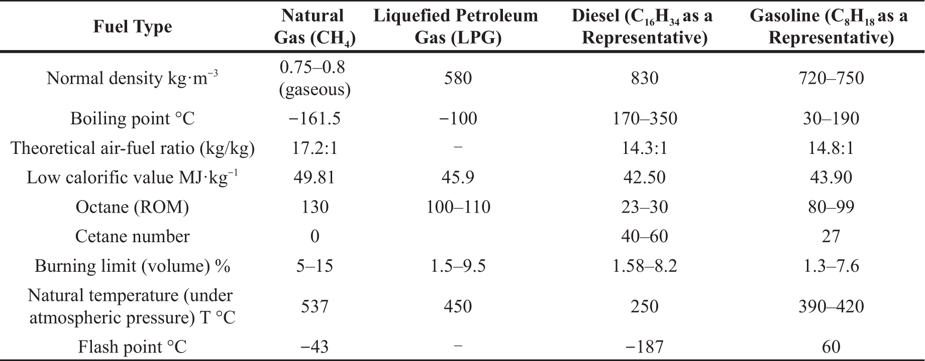
In Table 1, the octane number refers to the volume fraction of isooctane contained in a standard fuel with the same explosive resistance as gasoline. And the low calorific value refers to the heat released when the flue gas is cooled to its original temperature after 1 cubic meter of gas is completely burned, but the water vapor in the flue gas is still in the state of steam.
2.2.2. Shale Gas
Natural gas in absorbed and dissociated status is referred to as shale gas, which mainly exists in the rich organic matter shale and its interlayer. Therefore, shale gas is a clean and high efficient energy resource with methane as its major chemical composition. Compared to the conventional fossil based natural gas, shale gas is called the unconventional natural gas [ 21].
In recent years, more and more shale gas reserves were found in many countries. With the mature of exploration and development technologies of shale gas, its production has increased rapidly and drastically [ 22]. The major reserve countries worldwide have put more and more efforts on shale gas exploration and development.
Besides, shale gas has the advantage of long extraction life and long production cycles [ 23]. Shale hydrocarbon sources are often widely distributed in different thickness in basin areas. Each formation and enrichment of shale gas has its own unique characteristics. Generally, most shale gas wells can produce gas at a stable rate over a long period of time.
2.2.3. Combustible Ice
Natural gas hydrate is an ice like crystalline substance formed by natural gas and water under high pressure and low temperature conditions, which is called "combustible ice", as it looks like ice and burns when it meets fire. Natural gas hydrate deposits under the deep sea or land in the permafrost, with abundant reserves [ 24, 25]. It generates only a small amount of carbon dioxide and water after burning, and the pollutant emissions is far less than coal, or oil. It is thereby recognized worldwide as the replacement of energy resources, i.e., oil. Combustible ice is not ice, but a naturally occurring compound with a cage like microstructure. Combustible ice, as it is commonly known, has a structure that looks like ice and can burn when exposed to fire. Therefore, this kind of natural gas hydrate is also called "solid gas" or "gas ice".
3. Natural Gas Engines
Natural gas is a clean fuel. The pollutant emissions of NGEs are much lower than those of gasoline or diesel engines. For example, compared to gasoline engines, the exhausts of NGEs contain no sulfide or lead, and the carbon monoxide is reduced by 80 percent, hydrocarbons by 60 percent, and nitrogen oxides by 70 percent. As a result, many countries have taken the development of NGVs as the important means of reducing air pollution [ 26].
NGEs have significant economic benefits. They can reduce the operating cost of automotive vehicles [ 27]. At present, the price of natural gas is much lower than that of gasoline or diesel fuel. The fuel expenses can be generally reduced by more than 50 percent if using natural gas. Due to the price difference between gasoline or diesel and natural gas, the cost of upgrading from a gasoline or diesel vehicle to an NGV can be recouped in a few months.
The maintenance costs of NGEs can be reduced. After the engine uses natural gas as fuel, the engine service life can be prolonged, due to its smooth operation, low noise, and no carbon accumulation. The lubricating oil and spark plug of gasoline engines can be carried over by NGEs, so that it can save more than 50 percent of the maintenance cost [ 28, 29].
NGVs are safer than gasoline vehicles [ 30]. First of all, natural gas has a high ignition point (above 650 °C), 223 °C higher than the gasoline ignition point (427 °C), so that it is not easy to ignite compared with the gasoline. Secondly, the density of the natural gas is low, with a relative density of 0.48 to air. The natural gas leaked can be dispersed quickly into the air, making it difficult to form a concentration that burns on fire. And then, the natural gas octane number is up to 130, much higher than the current best auto ignition octane number of 96 in engines, which thereby has good anti-explosion performance. Next, the natural gas has a narrow explosion limit, only 5–15% in the natural environment. Therefore, it is very difficult to form this condition. When compressed natural gas leaking from a container or pipeline, the release process of the high pressure gas is a heat absorption process and a low temperature zone is quickly formed around the draining hole, making it difficult to ignite the nature gas. Finally, more accessories are required to use in CNG engines than those in gasoline engines.
The strict technical standards for NGVs have been set up in many countries. These technical standards cover many areas, from the design of the filling stations, the production of gas storage cylinders [ 31], and the manufacturing of modified vehicle parts, the installation and commissioning of NGVs. Strict security precautions should be considered in the design [ 32]. For the parts used in high pressure system of NGVs, the safety factors are selected 1.5–4 or above. A safety valve is installed on the pressure regulator and the gas cylinder, and emergency gas shut off devices are installed in the control system. Special inspection should be carried out before the gas cylinder leaves the factory. After the conventional inspections, the gas cylinder needs to be inflated for the tests of fire, explosion, falling, shooting and others. Only after all qualified, can it be used in the factory [ 33].
3.1. Mechanism of Natural Gas Engines
The mechanism of NGEs is similar to that of gasoline or diesel engines, except for the fuel used. Some structural redesign and new devices are required for NGEs [ 34, 35]. The following will explain some of the major changes in details.
In general, NGEs use LNG or CNG. The working mechanism of an LNG engine is shown in Figure 1.
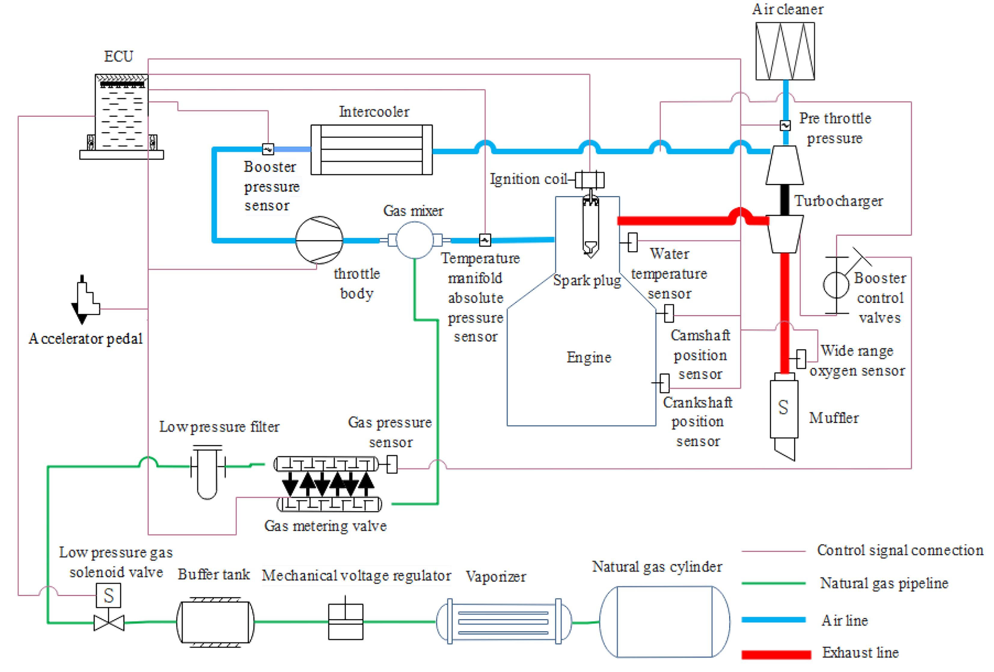
Figure 1. Working principle of liquefied natural gas (LNG) engine.
LNG enters the vaporizer from the gas cylinder to get heated and vaporized, and then enters the buffer tank after going through the voltage regulators. Once through the low pressure gas shut off valve and the low pressure filter, the gas is provided to the gas rail assembly controlled by the gas metering valve. The engine ECU controls the gas metering valve according to the engine operating conditions. So quantitative natural gas is provided to the air gas mixer, mixed with the air from the throttle, and a uniform air gas mixture is formed and supplied to engine for combustion.
The working mechanism of CNG engines is similar to that of LNG engines. The only difference is that the CNG fuel out of the gas cylinder is in high pressure gaseous status. The CNG through the high pressure solenoid valve and gas filter is decompressed to 7–8 bar in the decompressor with heat exchanger, then goes into the gas rail assembly (gas metering valve).
3.2. The Basic Structure of Natural Gas Engines
NGEs are carried over from the original gasoline or diesel engines. Considering the gaseous status characteristics of natural gas, the structures are redesigned in order to use natural gas effectively [ 36]. The design of neat gaseous fuel engines is generally divided into two categories. One is the gasoline-engine-based improvement design, and the structural changes are small. The other is the diesel-engine-based improvement design [ 37]. Compared with the design change of gasoline engines, the structure changes of diesel engines are large. The original injection system of diesel engines is removed. Instead, a set of ignition system is added. The engine compression ratio and other parameters are also changed. The cylinder head, piston, intake and exhaust system are redesigned either. The pressurization system is also needed to be re-matched.
For the NGEs stemmed from the improvement design of diesel engines, the major structure and parameter changes from original diesel engines are listed as follows.
(1) The fuel injection system of diesel engines including high pressure fuel pump, injectors, high pressure fuel pipes, and other parts is eliminated. Instead, the natural gas supply system including the intake valve, gas metering valve, air gas mixer and other parts is installed on the vehicle. And the gas solenoid valve, gas filter, vaporizer, pressure stabilizer (decompressor for CNG), buffer tank, etc. are added.
(2) The ignited combustion system is used in which the injector mounting holes in cylinder head of the diesel engine are changed to the spark plug mounting holes. The ignition control system is added, including the ignition control module ICM, ignition coil, high voltage lines, and spark plugs.
(3) In order to prevent knock, the compression ratio is smaller than that of the diesel engine, and the combustion chamber configuration in piston is different from the diesel engine.
(4) The signal generator is added, which is used to measure the engine speed.
(5) The mixer and the throttle are added, so that gas and air in the mixer are fully mixed. The throttle is used to control the power output from the engine.
(6) The exhaust temperature is high, and the supercharger adopts the water cooled intermediate shell. Wear resistant and high temperature resistant materials are used for the inlet and exhaust door seats, and the exhaust pipe is covered by the insulation materials.
(7) Compared with the diesel engine, the air fuel ratio is small, and less air is needed for the same power output.
3.3. Natural Gas Engine Control System
Many electronic control systems have been involved in contemporary automobiles, and the most important one of them is the engine control system [ 38]. For NGVs, the engine control system involves many subsystems of fuel control, air control, wire control, intake pressure control, exhaust gas bypass control, and ignition control.
3.3.1. Fuel Control
The fuel control system of LNG engines is composed of the LNG cylinder, vaporizer, pressure regulator, buffer tank, low pressure gas solenoid valve, low pressure gas filter, gas metering valve, mixer, oxygen sensor, and ECU. The role of the fuel control system of LNG engines is to convert the liquid status of LNG into the gaseous status at constant temperature and pressure [ 39], and supply the precise amount of natural gas to the mixer by using the gas metering valve based on the NGE operation conditions. The natural gas fully mixes with air in the mixer, and then the air gas mixture enters the NGE cylinder for combustion. The impurities in natural gas are filtrated by the gas filter to make the natural gas meet the clean requirements before entering the fuel metering valve. The required gas pressure is kept by using the pressure regulator after the LNG gasification. The engine coolant is used in the carburetor to heat the liquid natural gas and vaporize the liquid natural gas into gaseous status. The buffer tank volume is big enough to make the natural gas stable at the required gas pressure. The low pressure gas solenoid valve is used to cut off the natural gas supply after the engine stalls. The oxygen sensor is used to monitor the air gas ratio of the mixture entering the engine by collecting the oxygen concentration in the engine exhaust. All of the above functions are controlled by the ECU.
For the CNG engines, the fuel control system uses some different components from the LNG engines, i.e., the CNG cylinder, high pressure and low pressure gas filters, high pressure gas solenoid valve, gas decompressor [ 40]. At the same time, some components are carried over from the LNG engines, i.e., the gas metering valve, mixer, oxygen sensor, and ECU. The decompressor is used to reduce the pressure of the natural gas in the CNG cylinder to the appropriate pressure values of 5-20 MPa required by the gas metering valve, and to keep the reduced gas pressure constant.
3.3.2. Air Control
The air control system is used to control the air flow, as shown in Figure 2. Its main components include the electronic throttle, waste bypass control valve, foot pedal, temperature and manifold absolute pressure (TMAP) sensor, pre-throttle pressure (PTP) sensor, and other components [ 41]. The TMAP sensor is installed on the air inlet pipe behind the electronic throttle to measure the air inlet pressure and temperature. The engine ECU calculates the air intake flow of the engine through the signals obtained from the sensors, and determines the amount of natural gas to be supplied. At the same time, it also provides a measurement value for controlling the pressure of pressurization. The PTP sensor is installed in front of the throttle and used only to measure the pressure as a modified parameter for calculating the air flow into the engine, providing a benchmark for the charge volumetric efficiency (VE) involving the gas volume correction.
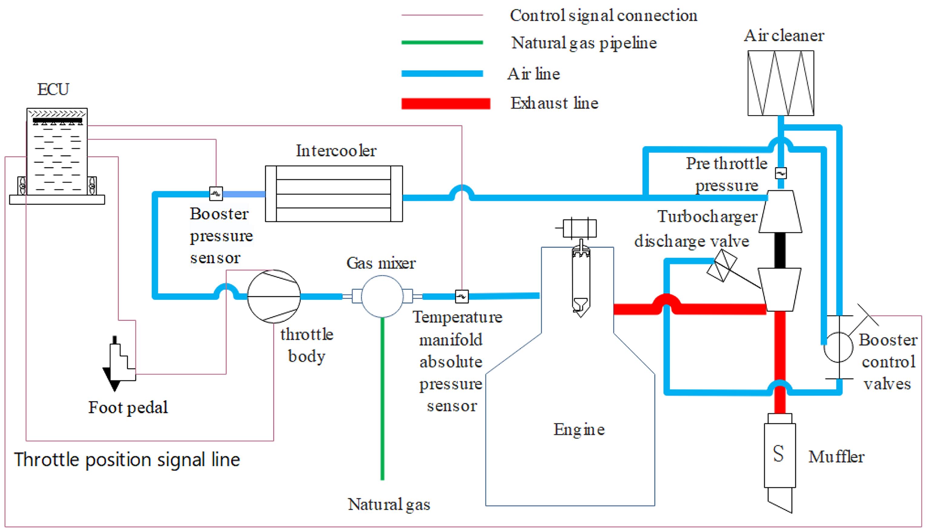
Figure 2. Air control system.
3.3.3. Wire Control
The wire control system, as shown in Figure 3, consists of an electronic throttle, an ECU, and a foot pedal. When the pedal is pressed, the ECU receives the throttle position signal to control the opening of the throttle. At the same time, the electronic throttle feeds the actual opening value to the ECU.
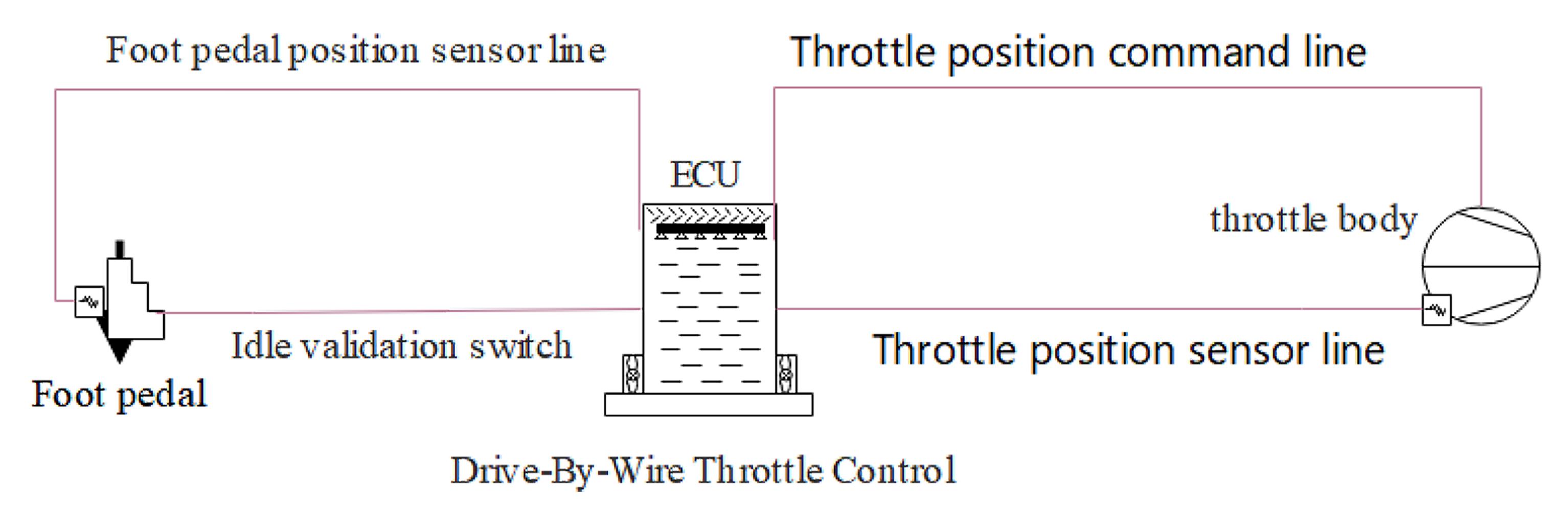
Figure 3. Control system by wire.
The main role of the electronic throttle is to control the air flow, engine idle, and maximum engine speed. The ECU controls the action of the throttle through a pulse width modulation (PWM) signal at a certain frequency, and its working stroke is limited by the ECU to 10–90% of the opening (the opening of the butterfly valve) range.
Based on the ECU instructions, the electronic throttle has three working states typically. When the engine speed is below the idling target value, the ECU performs idle control, that is, controls the throttle opening position to keep the engine speed near the idling target value. When the engine speed exceeds the maximum rated speed, the ECU limits the throttle opening position and controls the limit of the maximum engine speed. When the engine speed is between idle speed and the maximum rated speed, the throttle opening position changes synchronously with the foot pedal position. The electronic throttle should be installed in a low temperature area as far away from heat source as possible, according to the direction sign.
3.3.4. Intake Pressure Control
As shown in Figure 4, The intake pressure control system is composed of the turbocharger, waste bypass control valve, and manifold absolute pressure (MAP) sensor. At high loads, the actual pressure is controlled to the set pressure value.

Figure 4. Intake pressure control system.
The NGE turbocharger is different from that in diesel engines. It is a water cooled intermediate shell turbocharger with a pressure regulator. The water is used to cool down the lubricating oil in the oil chamber of the turbocharger to match the characteristics of high exhaust temperature in NGEs [ 42].
3.3.5. Exhaust Gas Bypass Control
The exhaust gas bypass control valve is connected to the pressure regulator of the turbocharger. Using the PWM signal, the ECU controls the exhaust valve switch's duty ratio to adjust the pressure above the pressure of regulator diaphragm. The exhaust vent valve opening could be controlled within a certain range, so that the goal of engine turbocharging pressure control could be achieved.
3.3.6. Ignition Control
The ignition control system is shown in Figure 5, which includes the engine ECU, the ignition control module, ignition coils, high voltage wires, and spark plugs.

Figure 5. Ignition system. (ECU: electronic control unit; ICM: ignition control module)
The function of the speed sensors, including the crankshaft and camshaft signal sensors, is to transmit the speed and engine piston top dead center (TDC) signal to the engine ECU, which is used to accurately control the air intake flow, natural gas amount, ignition advance angle, and so on. The control of these parameters requires the engine ECU to accurately collect the positions of the engine crankshaft and camshaft in the cylinder on fire, and the engine speed [ 43].
The ignition control module (ICM) is the actuator of the engine control system. Its function is to control the primary winding circuit of the ignition coil on and off according to the ignition command signal from the ECU [ 44], so that the secondary coil generates an instantaneous high voltage, which is transmitted to two electrodes of the spark plug. It causes the ionization of the air between the poles to generate sparks to ignite the air gas mixture for combustion. Besides, the sensors of water temperature, humidity, and exhaust temperature are also involved.
3.4. Technologies Used in Natural Gas Engines
After years of exploration and research by scholars and engineers, the great progress of technologies in NGEs have been made [ 45]. These technologies include the heterogeneous compression combustion, homogeneous charge compression ignition (HCCI) [ 46], dual fuel (natural gas and diesel) combustion, Miller cycle, long stroke, exhaust gas recirculation (EGR), and a combination of these technologies.
3.4.1. Heterogeneous Compression Combustion
High pressure natural gas is injected directly into the cylinder before the engine piston TDC and mixed with air. When the piston compresses the mixture continuously at a certain time before the TDC, the mixture is going to auto ignition itself, which is defined as the heterogeneous compression combustion, and the following flame propagation is called the diffusion combustion. This type of combustion can achieve thermal efficiency equivalent to that of diesel engines after using relatively high compression ratio. Controlling the amount of natural gas injection and adjusting the mixture concentration can make up for the poor performance of the traditional engines with the natural gas injection into the intake manifold under low loads [ 47]. In addition, the direct injection of natural gas into cylinder removes the throttle in the intake pipe, so that there is no intake throttling loss and volumetric efficiency loss, which improves the engine performance. It is possible to form a more homogeneous mixture than that in gasoline and diesel engines. The explosion resistance of combustion is improved due to the high octane number. Therefore, the engine can adopt a relatively higher compression ratio, which can improve the effective thermal efficiency of NGEs, easily realizing the compression combustion mode [ 48].
3.4.2. Dual Fuel (Natural Gas and Diesel) Combustion
All the components and functions of the original diesel engine are retained, and a set of natural gas supply devices is added. As a result, a dual fuel combustion system is formed, in which the natural gas is used as the main fuel. When the natural gas is compressed to near the TDC, a small amount of diesel is injected into the cylinder to form combustion flame under high pressure and temperature in the manner of conventional diesel engine ignition, which ignites the natural gas. This kind of engine can use neat diesel for combustion, and can also use both natural gas and diesel to achieve dual fuel combustion, which not only reduce the engine pollutant emissions, but also improve the thermal efficiency of combustion [ 49– 52].
3.4.3. Miller Cycle Technology
The Miller cycle technology is usually implemented by closing the engine intake valve early or late, resulting in less air entering the cylinder, so that the effective expansion stroke is greater than the effective compression stroke. This technology can reduce the effective compression ratio, as well as the temperature and pressure in the cylinder at the end of compression, so that the natural gas can be fully burned in the expansion stroke, followed by inhibiting the generation of emissions, and reducing the exhaust temperature. Miller cycle technology is used in conjunction with high supercharging of air intake. The increase of air intake pressure makes up for the reduction of air intake volume caused by early or late valve closing [ 53, 54].
3.4.4. Other Technologies in Cylinder
As the term suggests, long stroke technology means to make the engine compression and expansion stroke longer than normal. The natural gas and air in the cylinder have more time to mix evenly and to burn more completely. This technology not only reduces the engine speed, followed by reduction of the friction loss, but also increases the combustion thermal efficiency of NGEs. In addition, exhaust gas recirculation (EGR) technology works by reintroducing a portion of the burned exhaust gas into the cylinder and burning it with the mixture. Because the CO 2 in the exhaust gas belongs to a triatomic molecule with large heat capacity, which can lower down the combustion temperature in the cylinder, inhibiting the production of harmful NOx emissions [ 55– 58].
3.4.5. Other Out of Cylinder Technology
At present, in order to meet the automotive regulation requirements of fuel consumption and exhaust emissions, several out of cylinder technologies are very effective, which are called the after treatment technologies, including the oxidation catalysts (DOC), diesel particulate filter (DPF), and selective catalytic reduction (SCR). The major function of DOC is to convert hydrocarbon (HC) and carbon monoxide (CO) into carbon dioxide (CO 2) and water (H₂O). The DPF can collect the particulate matter (PM) of exhaust emissions, and burn it in the DPF. The SCR is a chemical process converting nitrogen oxides (NOx) into molecular nitrogen and water, i.e., converting hazardous NOx emissions from NGEs into harmless nitrogen and water [ 59– 63].
3.5. Application of Natural Gas Engine
Natural gas engines are widely used currently in transportation, electricity generation, refrigeration/air conditioning/heating and drilling platforms. Continuously improving the technology of natural gas engine, giving full play to the characteristics of natural gas engine will further promote NGE’s application and realize the goal of energy saving and emission reduction.
3.5.1. Using Natural Gas Engine to Drive Vehicles
Natural gas engines can be categorized by the fuel type as single fuel engines and dual fuel engines, or by the methods of fuel supply in vehicle applications. Using natural gas as an alternative energy source for vehicles can save fuel cost and solve the problem of vehicle exhaust pollution. At present, natural gas engines are widely used in buses, taxis, trucks and cars. But the market share is still small. To increase the application of natural gas engines, there are a lot of work to do, including special focus on reducing the cost of retrofitted engine and building more natural gas refueling stations.
3.5.2. Application of Natural Gas Engine on Electricity Generation
Generator sets driven by natural gas engines can realize the energy conversion, and effectively provide electric energy along with heat energy. Its comprehensive energy utilization rate can reach to above 85%. The cogeneration systems driven by natural gas engines can improve energy efficiency by using the waste heat. So, the systems have great energy saving potential and better energy economy. In the case of increasingly energy demanding tense, it is of great significance to improve energy utilization [ 64, 65].
3.5.3. Application of Natural Gas Engine on Refrigeration and Heating
Using natural gas engine instead of motor to directly drive refrigeration compressor can achieve the expected refrigeration effect. It has the characteristics of high energy utilization rate, safe and reliable in operation. It is also convenient to combine with other air conditioning systems, which can reduce the emission of carbon dioxide and sulfide, and is beneficial to environmental protection. The heat pump and compressor driven by natural gas engine can achieve the dual-purpose of heating and air conditioning, and the temperature in room can quickly reach to a comfortable level which not only has good heating effect, but also has low power consumption and high operation efficiency [ 66, 67].
3.5.4. Application of Natural Gas Engine on Drilling Platform
The natural gas engines designed and developed independently by Jinan Diesel Engine Company of China can meet the needs of the drilling platforms. Those natural gas engines run with good performance. Compared with diesel engines, they not only save expenses with energy conservation, but also reduces carbon emissions with low carbon level.
4. Conclusions
This review introduces the types of natural gas resources, focuses on the three development stages of natural gas engines, including fundamental knowledge underlying their structural design and combustion optimization. The electronic control system of natural gas engine, and the technologies which can be applied to natural gas engine are discussed respectively. Based on the above discussion, it is concluded that natural gas has been successfully applied to internal combustion engines in different fields such as automobiles, generator sets, refrigeration/air conditioning and heat pumps. At the same time, natural gas is becoming a promising alternative fuel to gasoline or diesel in internal combustion engines due to its advantages such as the excellent knock resistance, stable combustion process, cost benefits, and low pollutant emissions. It is expected that more and more natural gas vehicles will be on road, and the combinations and optimizations of new technologies will be used in natural gas engines.
Author Contributions: Conceptualization, L.L.; writing—original draft preparation, L.L, M.Z, Z.L.; writing—review and editing, L.L., M.L. All authors have read and agreed to the published version of the manuscript.
Funding: This research was funded by Basic Science Research Project of Colleges and Universities of Education Department of Liaoning Province (Project No. LJKZ0608).
Data Availability Statement: Not applicable.
Conflicts of Interest: The authors declare no conflict of interest.
References
- Li F.B. ; Wang Z. ; Wang Y.F. ; et al . High-efficiency and clean combustion natural gas engines for vehicles. Automotive Innovation, 2019, 2( 10): 284- 304. DOI: https://doi.org/10.1007/s42154-019-00075-z
- Gas Engine Market to Grow at 7% CAGR Worldwide 2014 - 2019. M2 Presswire, 2015. Available Online: https://www.proquest.com/wire-feeds/gas-engine-market-grow-at-7-cagr-worldwide-2014/docview/1713967394/se-2 (Accessed on 5 March 2023).
- Gazprom gas-engine fuel to open 16 CNG filling stations in leningrad region by end of 2020-governor. Interfax: Russia & CIS energy newswire, 2019. Available Online: https://interfax.com/newsroom/top-stories/19648/ (Accessed on 5 March 2023).
- Kuang Y.M. ; Lin B.Q. Natural gas resource utilization, environmental policy and green economic development: Empirical evidence from China. Resources Policy, 2022, 79: 102992. DOI: https://doi.org/10.1016/j.resourpol.2022.102992
- U . S. Energy Information Administration. Crude oil and natural gas resource development. Washington, DC: U. S. Energy Information Administration, 2023. Available Online: https://www.eia.gov/totalenergy/data/monthly/pdf/sec5_n.pdf (Accessed on 2 March 2023).
- Johnson R.L. , Jr.; Hopkins C.W. ; Zuber M.D. Technical challenges in the development of unconventional gas resources in Australia. The APPEA Journal, 2000, 40( 1): 450- 468. DOI: https://doi.org/10.1071/AJ99026
- Wiesbaden, S.F. “Current gas engine developments WILL set the pattern for the next 30 years”. MTZ industrial, 2014, 4( 2): 20- 23. DOI: https://doi.org/10.1007/s40353-014-0135-8
- Pan K. ; Wallace J. Soot and combustion models for direct-injection natural gas engines. International Journal of Engine Research, 2022, 23( 1): 150- 166. DOI: https://doi.org/10.1177/1468087420978014
- Muhssen H.S. ; Masuri S.U. ; Sahari B.B. ; et al . Design improvement of compressed natural gas (CNG)-air mixer for diesel dual-fuel engines using computational fluid dynamics. Energy, 2021, 216: 118957. DOI: https://doi.org/10.1016/j.energy.2020.118957
- Kim S. ; Park C. ; Jang H. ; et al . Effect of boosting on a performance and emissions in a port fuel injection natural gas engine with variable intake and exhaust valve timing. Energy Reports, 2021, 7: 4941- 4950. DOI: https://doi.org/10.1016/j.egyr.2021.07.073
- Li M.H. ; Liu G.F. ; Liu X.R. ; et al . Performance of a direct-injection natural gas engine with multiple injection strategies. Energy, 2019, 189: 116363. DOI: https://doi.org/10.1016/j.energy.2019.116363
- Li M.H. ; Zheng X.L. ; Zhang Q. ; et al . The effects of partially premixed combustion mode on the performance and emissions of a direct injection natural gas engine. Fuel, 2019, 250: 218- 234. DOI: https://doi.org/10.1016/j.fuel.2019.04.009
- Li M.H. ; Wu H.M. ; Liu X.R. ; et al . Numerical investigations on pilot ignited high pressure direct injection natural gas engines: a review. Renewable and Sustainable Energy Reviews, 2021, 150: 111390. DOI: https://doi.org/10.1016/j.rser.2021.111390
- Cruz C.S. ; Stimpson S. Keeping the lights on: oil and gas development in a low-carbon world. Journal of Energy & Natural Resources Law, 2022, 40( 4): 491- 494. DOI: https://doi.org/10.1080/02646811.2022.2093007
- Zhang H. ; Yin D.D. The oil and gas industry and the development of the natural gas automobile industry. IOP Conference Series: Earth and Environmental Science, 2019, 267( 2): 022043. DOI: https://doi.org/10.1088/1755-1315/267/2/022043
- Ogle, S. Natural gas compression empowering energy evolution. Pipeline & Gas Journal, 2022, 249( 9). Available Online: https://pgjonline.com/magazine/2022/september-2022-vol-249-no-9/guest-commentary/natural-gas-compression-empowering-energy-evolution (Accessed on 2 March 2023)
- Huang S. ; Xiong S.T. ; Zhao Z.G. Discussion about the Cr-Mo steel materials using in CNG cylinders. Materials Science Forum, 2020, 1001: 235- 239. DOI: https://doi.org/10.4028/www.scientific.net/MSF.1001.235
- Gao, L.S. Design and manufacture of composite CNG cylinders. Applied Mechanics and Materials, 2014, 670/671: 955- 959. DOI: https://doi.org/10.4028/www.scientific.net/AMM.670-671.955
- Banaszkiewicz T. ; Chorowski M. ; Gizicki W. ; et al . Liquefied natural gas in mobile applications—opportunities and challenges. Energies, 2020, 13( 21): 5673. DOI: https://doi.org/10.3390/en13215673
- Kim C.U. ; Bae C.S. Speciated hydrocarbon emissions from a gas-fuelled spark-ignition engine with various operating parameters. Proceedings of the Institution of Mechanical Engineers, Part D: Journal of Automobile Engineering, 2000, 214( 7): 795- 808. DOI: https://doi.org/10.1243/0954407001527655
- Sinopec makes Sichuan Basin shale gas discovery. Oil & Gas Journal 2022, 120(10d). Available Online: https://www.ogj.com/exploration-development/discoveries/article/14284699/sinopec-makes-sichuan-basin-shale-gas-discovery (Accessed on 5 March 2023).
- Dong D. ; Wang Y. ; Li X. ; et al . Breakthrough and prospect of shale gas exploration and development in China. Natural Gas Industry B 2016, 3( 1), 12- 26. DOI: https://doi.org/10.1016/j.ngib.2016.02.002
- Zou C. ; Dong D. ; Wang Y. ; et al . Shale gas in China: Characteristics, challenges and prospects (II). Petroleum Exploration and Development 2016, 43( 2), 182- 196. DOI: https://doi.org/10.1016/S1876-3804(16)30022-2
- Anonymous . Combustible ice reserves in South China Sea's Shenhu block total 19. 4 bln cubic meters. Interfax: China Energy Newswire 2010. Available Online: https://schlr.cnki.net/zn/Detail/index/GARJ0010_6/SPQD00003781806 (Accessed on 5 March 2023).
- Editorial Department of this Journal . The second-round trial collection of natural gas hydrate (combustible ice) in China's sea areas achieves complete success. Geology in China, 2020, 47( 2): 555.
- Arkansas selects diesel-to-natural gas engine. Worldwide Energy, 2014, 26( 6). Available Online: https://www.proquest.com/trade-journals/arkansas-selects-diesel-natural-gas-engine/docview/1535683013/se-2 (Accessed on 5 March 2023).
- Soltani-Sobh A. ; Heaslip K. ; Bosworth R. ; et al . Compressed natural gas vehicles: financially viable option? Transportation Research Record, 2016, 2572( 1): 28- 36. DOI: https://doi.org/10.3141/2572-04
- Yi P. ; Long W.Q. ; Feng L.Y. ; et al . Investigation of evaporation and auto-ignition of isolated lubricating oil droplets in natural gas engine in-cylinder conditions. Fuel, 2019, 235: 1172- 1183. DOI: https://doi.org/10.1016/j.fuel.2018.08.084
- Li L.F. ; Zhang Z.B. Investigation on steam direct injection in a natural gas engine for fuel savings. Energy, 2019, 183: 958- 970. DOI: https://doi.org/10.1016/j.energy.2019.06.182
- Sarabi M. ; Aghdam E.A. Experimental analysis of in-cylinder combustion characteristics and exhaust gas emissions of gasoline–natural gas dual-fuel combinations in a SI engine. Journal of Thermal Analysis and Calorimetry, 2020, 139( 5): 3165- 3178. DOI: https://doi.org/10.1007/s10973-019-08727-2
- Chamberlain S. ; Chookah M. ; Modarres M. Development of a probabilistic mechanistic model for reliability assessment of gas cylinders in compressed natural gas vehicles. Proceedings of the Institution of Mechanical Engineers, Part O: Journal of Risk and Reliability, 2009, 223( 4): 289- 299. DOI: https://doi.org/10.1243/1748006XJRR231
- Khan M.I. ; Yasmin T. ; Khan N.B. Safety issues associated with the use and operation of natural gas vehicles: learning from accidents in Pakistan. Journal of the Brazilian Society of Mechanical Sciences and Engineering, 2016, 38( 8): 2481- 2497. DOI: https://doi.org/10.1007/s40430-015-0410-9
- Kim Y.S. ; Park K.S. ; Kim T.O. Suggestion for safety improvement of compressed natural gas vehicle. Journal of the Korean Institute of Gas, 2012, 16( 4): 1- 7. DOI: https://doi.org/10.7842/kigas.2012.16.4.1
- Wei Z.N. ; Li M.H. ; Li S. ; et al . Development of natural gas chemical kinetic mechanisms and application in engines: a review. ACS Omega, 2021, 6( 37): 23643- 23653. DOI: https://doi.org/10.1021/acsomega.1c03197
- Pan K. ; Wallace J.S. A low temperature natural gas reaction mechanism for compression ignition engine application. Combustion and Flame, 2019, 202: 334- 346. DOI: https://doi.org/10.1016/j.combustflame.2019.01.024
- Matsuoka H. ; Kishishita K. ; Nakashima K. ; et al . Structure and performance of heat insulated natural gas engine. JSAE Review, 1997, 18( 4): 377- 384. DOI: https://doi.org/10.1016/S0389-4304(97)00028-3
- Shi J.L. ; Li T. ; Liu Z.C. ; et al . Life cycle environmental impact evaluation of newly manufactured diesel engine and remanufactured LNG engine. Procedia CIRP, 2015, 29: 402- 407. DOI: https://doi.org/10.1016/j.procir.2015.01.029
- Noble A.D. ; Beaumont A.J. Control system for a low emissions natural gas engine for urban vehicles. New York: SAE International, 1991. DOI: https://doi.org/10.4271/910255
- Smith H. ; Pipeline T.G. ; Wachowiak R. ; et al . Fuel control system updates older natural gas engines. Pipeline & Gas Journal, 2012, 239( 1): 58- 62.
- Han Y. ; Young P. Natural gas engine model for speed and air-fuel control. International Journal of Modelling, Identification and Control, 2020, 36( 2): 104- 115. DOI: https://doi.org/10.1504/IJMIC.2020.116193
- Gubba S.R. ; Tamma B. ; Kazempoor P. ; et al . A novel air management system for a large bore two-stroke naturally aspirated gas engine to reduce emissions. International Journal of Engine Research, 2021, 22( 2): 364- 374. DOI: https://doi.org/10.1177/1468087419871858
- Thipse S.S. ; Dsouza A. ; Sonawane S.B. ; et al . Development of multi cylinder turbocharged natural gas engine for heavy duty application. SAE International Journal of Engines, 2017, 10( 1): 27- 38. DOI: https://doi.org/10.4271/2017-26-0065
- Che X.L. ; Zhu C. ; Wang N.D. Testing system for compressed natural gas engine ECU. Applied Mechanics and Materials, 2011, 127: 214- 219. DOI: https://doi.org/10.4028/www.scientific.net/AMM.127.214
- Wang X.L. ; Ping X. Hardware design of nature gas engine ECU based on single chip. Applied Mechanics and Materials, 2014, 575: 576- 579. DOI: https://doi.org/10.4028/www.scientific.net/AMM.575.576
- Zeng, Q. Study on the modification and performance of compressed natural gas engine. Applied Mechanics and Materials, 2014, 568/570: 1690- 1693. DOI: https://doi.org/10.4028/www.scientific.net/AMM.568-570.1690
- Shimizu R. ; Iijima A. ; Yoshida K. ; et al . Analysis of supercharged HCCI combustion using a blended fuel. SAE International Journal of Engines, 2012, 5( 1): 1- 8. DOI: https://doi.org/10.4271/2011-32-0521
- Xu M. ; Cheng W. ; Li Z. ; et al . Pre-injection strategy for pilot diesel compression ignition natural gas engine. Applied Energy, 2016, 179: 1185- 1193. DOI: https://doi.org/10.1016/j.apenergy.2016.07.024
- Ohta Y. ; Furutani M. ; Kojima M. ; et al . Premixed-compression-ignition natural gas engine. New York: SAE International, 2000.
- Mansor W.N.W. ; Abdullah S. ; Olsen D.B. ; et al . Diesel-natural gas engine emissions and performance. AIP Conference Proceedings, 2018, 2035( 1): 060010. DOI: https://doi.org/10.1063/1.5075590
- Worth D.J. ; Stettler M.E.J. ; Dickinson P. ; et al . Characterization and evaluation of methane oxidation catalysts for dual-fuel diesel and natural gas engines. Emission Control Science and Technology, 2016, 2( 4): 204- 214. DOI: https://doi.org/10.1007/s40825-016-0047-x
- Johnson D. ; Heltzel R. ; Nix A. Trends in unconventional well development—methane emissions associated with the use of dual fuel and dedicated natural gas engines. Energy Technology, 2014, 2( 12): 988- 995. DOI: https://doi.org/10.1002/ente.201402088
- Semin; Ismail A.R. ; Bakar R.A. Combustion temperature effect of diesel engine convert to compressed natural gas engine. American Journal of Engineering and Applied Sciences, 2009, 2( 1): 212- 216. DOI: https://doi.org/10.3844/ajeassp.2009.212.216
- Song S.S. ; Zhang H.G. Performance study for miller cycle natural gas engine based on GT-power. Journal of Clean Energy Technologies, 2015, 3( 5): 351- 355. DOI: https://doi.org/10.7763/JOCET.2015.V3.222
- Okamoto K. ; Zhang F.R. ; Shimogata S. ; et al . Development of a late intake-valve closing (LIVC) miller cycle for stationary natural gas engines - effect of EGR utilization. New York: SAE International, 1997. DOI: https://doi.org/10.4271/972948
- Valencia G. ; Duarte J. ; Isaza-Roldan C. Thermoeconomic analysis of different exhaust waste-heat recovery systems for natural gas engine based on ORC. Applied Sciences, 2019, 9( 19): 4017. DOI: https://doi.org/10.3390/app9194017
- Rink M. ; Eigenberger G. ; Nieken U. Heat-integrated exhaust purification for natural gas engines. Chemie Ingenieur Technik, 2013, 85( 5): 656- 663. DOI: https://doi.org/10.1002/cite.201200162
- Alanen J. ; Simonen P. ; Saarikoski S. ; et al . Comparison of primary and secondary particle formation from natural gas engine exhaust and of their volatility characteristics. Atmospheric Chemistry and Physics, 2017, 17( 14): 8739- 8755. DOI: https://doi.org/10.5194/acp-17-8739-2017
- Pirouzpanah V. ; Sarai R.K. Reduction of emissions in an automotive direct injection diesel engine dual-fuelled with natural gas by using variable exhaust gas recirculation. Proceedings of the Institution of Mechanical Engineers, Part D: Journal of Automobile Engineering, 2003, 217( 8): 719- 725. DOI: https://doi.org/10.1243/09544070360692104
- Lehtoranta K. ; Murtonen T. ; Vesala H. ; et al . Natural gas engine emission reduction by catalysts. Emission Control Science and Technology, 2017, 3( 2): 142- 152. DOI: https://doi.org/10.1007/s40825-016-0057-8
- Huang C.Y. ; Shan W.P. ; Lian Z.H. ; et al . Recent advances in three-way catalysts of natural gas vehicles. Catalysis Science & Technology, 2020, 10( 19): 6407- 6419. DOI: https://doi.org/10.1039/D0CY01320J
- Zheng J. ; Zhou R. ; Zhan R. ; et al . Combustion and emission characteristics of natural gas engine with partial-catalytic oxidation of the fuel. Fuel, 2022, 312: 122796. DOI: https://doi.org/10.1016/j.fuel.2021.122796
- Hora T.S. ; Shukla P.C. ; Agarwal A.K. Particulate emissions from hydrogen enriched compressed natural gas engine. Fuel, 2016, 166: 574- 580. DOI: https://doi.org/10.1016/j.fuel.2015.11.035
- Ristovski Z.D. ; Morawska L. ; Hitchins J. ; et al . Particle emissions from compressed natural gas engines. Journal of Aerosol Science, 2000, 31( 4): 403- 413. DOI: https://doi.org/10.1016/S0021-8502(99)00530-3
- Gas engine-driven cogeneration system. Air Conditioning Heating & Refrigeration News, 2012, 245( 17). Available Online: https://digital.bnpmedia.com/publication/?m=9388&i=108284&p=8&ver=html5 (Accessed on 5 March 2023)
- Sun, Z.G. Energy efficiency and economic feasibility analysis of cogeneration system driven by gas engine. Energy and Buildings, 2008, 40( 2): 126- 130. DOI: https://doi.org/10.1016/j.enbuild.2007.01.013
- Khaliq A. ; Almohammadi B.A. ; Alharthi M.A. ; et al . Investigation of a combined refrigeration and air conditioning system based on two-phase ejector driven by exhaust gases of natural gas fueled homogeneous charge compression ignition engine. Journal of Energy Resources Technology, 2021, 143( 12): 120911. DOI: https://doi.org/10.1115/1.4052248
- Mcdonough M.J. ; Lafaille S. Natural-gas-engine-driven heat pumps: technological advances lead to higher efficiency and lower emissions. HPAC Engineering, 2012, 84( 8): 36, 38, 40- 41.


