

Downloads
Download


This work is licensed under a Creative Commons Attribution 4.0 International License.
Article
Spark Plasma Stretching and Ignition Improvement via High Frequency Pulsed Current Boost
Linyan Wang , Xiao Yu , Zhi Yang Ong , Simon LeBlanc , and Ming Zheng *
Department of Mechanical, Automotive and Materials Engineering, University of Windsor, 401 Sunset Avenue, Windsor, N9B 3P4 Ontario, Canada
* Correspondence: mzheng@uwindsor.ca
Received: 9 May 2023
Accepted: 12 May 2023
Published: 19 June 2023
Abstract: In modern engines, the improvement of fuel efficiency and reduction of exhaust emissions have become increasingly important, with the consequent need for improved performance and advancement of ignition systems. The ignition mechanisms utilized in modern engines frequently encounter a fuel-lean or gas-diluted blend of substantial density and vigorous airflow. Under such conditions, the spark plasma is influenced by gas movements, specifically crossflows that occur in a voluminous manner. The gas motions can stretch the plasma channel, thereby amplifying the total discharge energy compared to quiescent conditions. It has been proven that an increased discharge current is an efficacious method for extending the duration of spark plasma stretching. Nevertheless, high discharge current can increase the energy consumption of ignition systems and consequently, influence the durability and overall energy efficiency of the system. Moreover, the persistent flow of intense electrical current leads to prompt erosion of the spark electrode, impacting the durability of the spark plug. In this study, a novel ignition strategy of high-frequency pulsed currents is introduced, to enhance the effectiveness of plasma stretching and energy discharge while minimizing the overall energy usage of ignition systems. A high-frequency pulsed discharge strategy is accomplished within the controlled duration without affecting the plasma stretching phenomenon. The plasma channel behaviors are logged using electrical and optical measurements. Furthermore, the discharge frequency and current level impacts of the boosted current pulses on the plasma stretching behavior and flame propagation are also investigated.
Keywords:
high power ignition systems spark energy efficiency pulsed high current boost spark plasma stretching spark plug durability1. Introduction
Internal combustion (IC) engines have been the main propulsion systems for automotive applications and are expected to remain the primary source of power for vehicular transportation, including hybrid vehicles, in the near to medium-term future [1]. The optimal strategy for addressing the challenge of greenhouse gas (GHG) emissions requires a carefully considered technology mix that is tailored to each corresponding application. This technology mix can include various options, such as electrical energy, hydrogen, E-fuels, and renewable fuels [2]. Efforts to enhance efficiency as well as embrace renewable energy sources are vital in reducing the carbon emissions of forthcoming sustainable powertrain systems [3]. Numerous techniques have been postulated to attain superior engine efficiency, notably lean-burn or exhaust gas recirculation (EGR) diluted combustion. These methods necessitate amplified in-cylinder charge movement to expedite the flame propagation process [4-6]. The dynamics of charge movement have a significant impact not only on flame propagation, but also on spark plasma patterns, spark energy release, and ultimately the ignition process [7]. Prior studies have provided evidence that the spark plasma channel can be stretched beyond the spark gap, thus leading to an extended length of the plasma channel and subsequently increasing the volume of ignition [8]. Following the enlargement in the plasma length, there is a concomitant amplificaftion in the voltage across the plasma channel, impacting the magnitude of energy release within the plasma channel [9]. Given the impact of plasma channel dynamics on ignition efficacy, a substantial number of researchers have undertaken studies into the behavior of plasma channels when subjected to gas-flow conditions.
Shiraishi et al. characterized the plasma channel stretching under different background pressures and gas flow velocities [10]. The authors reported that the maximum spark channel length before the first restrike was highly linked to the average discharge current. Yu et al. experimentally studied flame propagation with various discharge current levels under flow conditions [11]. The findings indicated that a boosted discharge current is capable of preserving a consistent discharge under flow conditions with a reduction in the number of restrikes and an extension in the duration of plasma retention. Zhu et al. [12] studied the relationship between the stretched plasma length and the rate of propagation of flames. It was observed that an increase in plasma stretch corresponded to a notable augmentation in the rate of flame propagation during the application of an identical control strategy. In another study conducted by Sayama et al. [13], an optical engine was fabricated to produce a flow velocity exceeding 40 m/s across the spark gap, simulating engine operating conditions. The findings indicated that increasing the spark energy leads to a marked reduction in the occurrences of restrike, thus favorably impacting the ignition process.
The results established in the aforementioned research reveal that to improve the persistence and stabilization of the spark plasma channel amidst amplified charge motion, increased discharge current, and higher energy are important for advanced ignition mechanisms. The utilization of higher discharge current necessitates higher power consumption of ignition systems, which in turn, leads to reduced energy transfer efficiency [14]. Moreover, the prolonged and sustained flow of high-current electricity results in pronounced and deleterious electrode erosion for the spark plug, thereby undermining its durability [15‒17]. In the authors’ research, it is observed from the high-speed images that the continuous high current boost causes the metal particles to burn out from the spark electrode. Considering the actual applications, the continuous higher discharge energy and discharge current also demand stricter electrical insulation and system cooling.
This study introduces an innovative method for the management of high-frequency pulsed current aimed at enhancing plasma stretching and energy discharge, while concurrently reducing the overall energy consumption of the ignition system. The implementation of a high-frequency pulsed current management strategy is accomplished without any disruption to the plasma stretching process. The ignition strategy is achieved via the precise control of the discharge signal, operating at levels of sub-microseconds, using field-programmable gate arrays (FPGA) and power electronics hardware. The properties of the plasma channel are logged through the utilization of electrical measurements alongside high-speed imaging techniques. An investigation is also conducted on the impact of distinct boost strategies, namely continuous and pulsed current, on both plasma stretching behavior and flame propagation. Furthermore, the discharge frequency and current level impacts of the boosted current pulses on the plasma stretching behavior and flame propagation are also investigated.
2. Experimental Setups
The experimental setups applied in this study comprise a constant volume combustion chamber system equipped with instruments for electrical and optical measurements of the spark plasma pattern and flame propagation.
2.1. Constant Volume Combustion Chamber System
A constant volume combustion chamber (CVCC) equipped with optical access has been used to regulate background conditions, as illustrated in Figure 1. The optical chamber with a fixed volume comprises a working volume of 0.2 L and features twin quartz windows with a Ø62 mm viewport. Concurrent imaging utilizing high-speed direct and shadowgraph methods has been implemented to visually observe the spark plasma pattern and the progression of ignition flame kernel formation. Photographs are captured through the use of high-speed cameras, Photron Nova S16 and Photron Mini AX200.
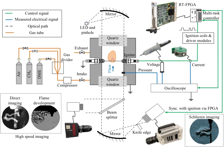
Figure 1. Ignition research platform with field-programmable gate arrays (FPGA) synchronized electrical and optical measurements.
The control and data acquisition system for the experiments consists of a National Instrument’s real-time (RT) computer with FPGA for ignition command generation, and a PicoScope 4824 oscilloscope for electric waveform recording. A Pearson 411 current transformer and a Tektronix P6015 voltage probe are used to measure the discharge current and voltage, respectively. During the experiments, transistor-transistor logic (TTL) spark command signals are sent from the FPGA for controlling the charging durations of the primary coil.
The combustion chamber is fitted with dynamic pressure transducers for combustion pressure measurement. Cross flow across the spark gap is generated by high-pressure air jets coming from a high-pressure tube. The high-pressure tube is connected to a high-pressure Nitrogen gas bottle, with a 400 mL buffer volume added between the bottle and the optical chamber to stabilize the gas pressure. An Environics 4040 gas divider is employed to provide accurate access air ratio control on the air-fuel mixture. All the control signals, including high-speed camera, oscilloscope, and TTL command are synchronized and adjusted by the multi-task FPGA system.
A pair of stainless-steel needles with a diameter of 1.0 mm are used as electrodes to form a spark gap. The spark gap size is 1.0 mm. The use of the needle electrode can reduce the impact of electrode geometry on flow field disturbance. To reduce the impacts of energy release from the spark initiation process, instead of using a traditional ignition coil, the spark plasma initiation is generated by a high voltage nanosecond generator (FID FPG 50-5NM10). In addition to the plasma initiation system, a current management module is applied to increase the discharge current level. The discharge current level of the current management system can be up to 3.5 A. The energy release from the high voltage capacitors shown in Figure 2 is controlled by a high-frequency high-power MOSFET which supports a current boost frequency of 100 kHz. The control command for the MOSFET is sent by the FPGA system. The simplified electrical circuit of the ignition system is shown in Figure 2 with the measurement locations for the discharge current and spark gap voltage.

Figure 2. Spark ignition system with current management module.
2.2. Spark Energy and Energy Efficiency Calculations
As shown in Figure 3, the utilization of a high voltage probe positioned between the secondary coil and the spark central electrode serves to quantify the voltage across the spark gap, Ugap. Based on the electrical measurements, the discharge power and energy can be calculated as presented in Equations (1) and (2).
where Ugap and Is are spark gap voltage and discharge current, respectively, tdischarge is the discharge duration.

Figure 3. Energy distribution of spark discharge with current management module.
During the current boost process, the discharge of energy from the high-voltage capacitors is separated into two primary resistances: external resistance and plasma channel resistance. The voltage across the spark gap has a direct correlation with the resistance of the plasma channel. Therefore, to examine the effects of various current boost strategies on the transmission of energy in the spark, it is necessary to calculate the resistance of the spark plasma as shown below in Equation (3),

The supplied energy of the current boost system is calculated using the discharge current and the voltage measured from the high-voltage capacitor as Usupply shown below in Equation (4):

Subsequently, the spark discharge efficiency is calculated as the ratio of the discharge and supply energies as shown below in Equation (5):

By the aforementioned relationships, a rise in plasma resistance facilitates an elevation in discharge efficiency.
3. Results and Discussion
3.1. Plasma Stretching Improvements via High-Frequency Pulsed Current Boost
Under flow conditions as illustrated in Figure 4, the plasma channel is stretched away from the crossing line of the spark gap by the flow. The plasma is stretched at a speed comparable to the airflow velocity across the spark gap. The spark plasma length, affected by different current boost strategies is calculated using high-speed imaging and image processing.

Figure 4. Definitions of plasma characteristics parameters.
The previously published experimental results [8,9,11,14,18] indicate a positive relationship between the spark gap resistance and the discharge voltage, to the stretched spark plasma channel. The restrike phenomenon is triggered when the discharge voltage is not adequate to sustain the spark channel. The occurrence rate of restrike rises in proportion to the increase in the flow velocity and the decrease in the discharge current level. A higher discharge current has been empirically established to be an efficacious method to extend the duration of the spark plasma stretching.
The current study explores the effects of high-frequency pulsed currents management on plasma stretch and spark discharge energy distribution in controlled flow conditions wherein nitrogen (N2) serves as the background gas. The high-speed imaging of the spark plasma, and the measurement of the discharge voltage and current, are performed simultaneously. The findings derived from Figure 5 suggest that the implementation of continuous current management with a discharge duration of 3 ms leads to the generation of a plasma channel that possesses greater width and luminosity, and remains stretched along the cross-flow.

Figure 5. Plasma stretching via continuous current boost (Current level 3 A, N2, flow velocity ~6 m/s).
Due to the high discharge current of 3 A and a comparatively low flow rate of 6 m/s, no occurrence of restrike is observed to disrupt the plasma stretching process. Upon the completion of the current boost process, the accompanying phenomenon of plasma stretching is also terminated. The detachment and dissipation of the plasma channel from the spark electrodes are observed to occur gradually within the surrounding mixture.
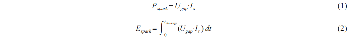
A novel high-frequency pulsed current boost strategy is suggested as a point of comparison with the traditional continuous current boost approach. As illustrated in Figure 6, the discharge current is measured through a high-frequency pulsed signal which oscillates between 0 to 3 A, by the frequency of the control signal from the FPGA.
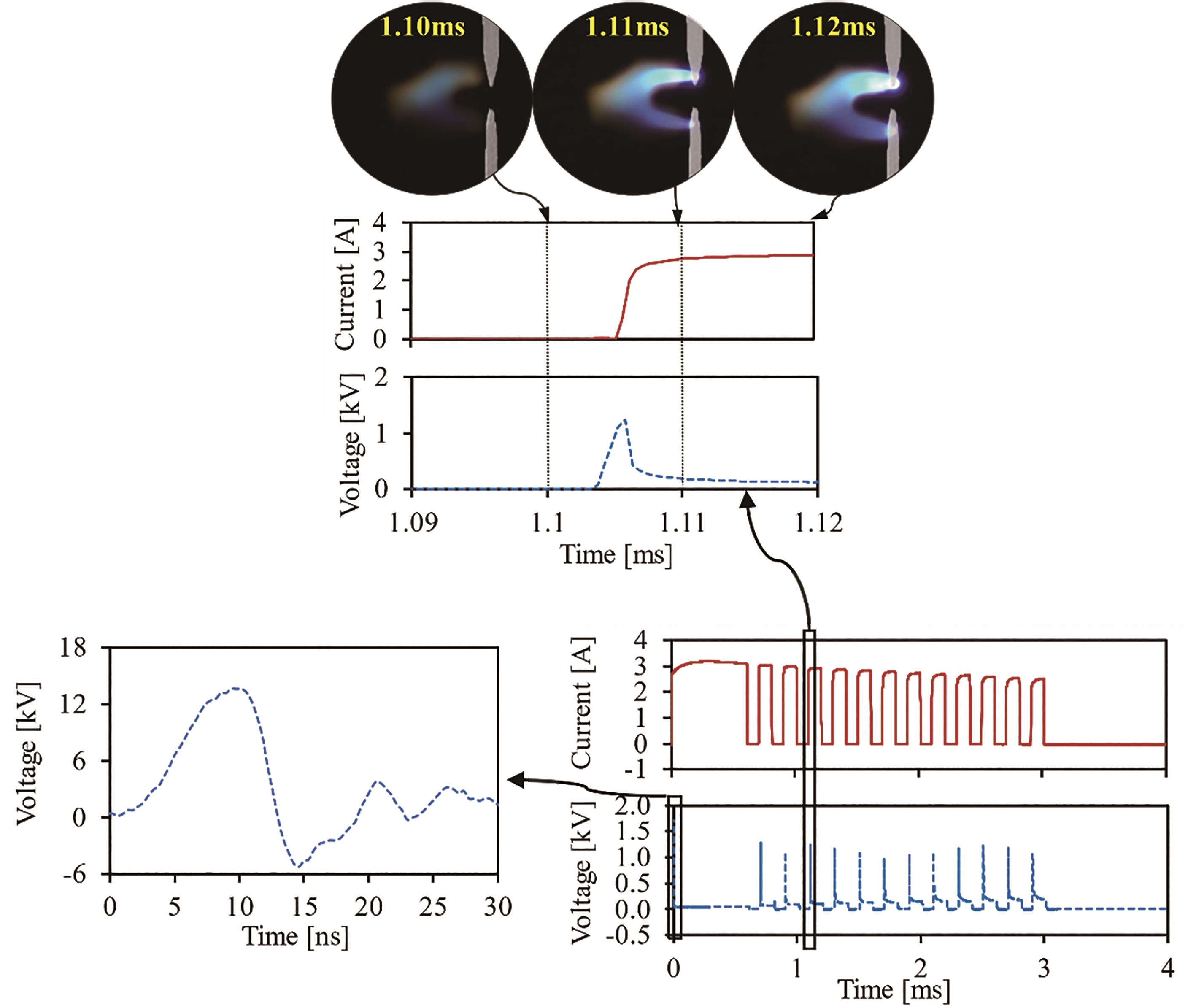
Figure 6. Electrical measurements and plasma pattern via high-frequency pulsed current boost.
A detailed analysis is conducted based on the results from the simultaneous electrical and optical measurements. At a specific temporal point of 1.1 ms post the initiation of the spark, plasma detaches from the electrodes as the boost current is cut off. As a result of the reaction time exhibited by various hardware components, including power electronics, capacitor charging systems, and measurement equipment, it requires around 50 µs for the discharge current to restore from a state of complete discharge to reaching a magnitude of 3 A. At 1.11 ms, a re-establishment of plasma is observed based on high-speed imaging. In contrast to the restrike phenomenon, the re-establishment of the plasma path does not involve the creation of a new plasma channel across the spark gap. Rather, this process is predicated on the preceding discharge cycle, thereby avoiding any disruption to the continued stretching of the plasma. Moreover, it has been observed that the magnitude of voltage required for plasma reestablishment through the application of pulsed current boost (~1.5 kV) is significantly lower compared to the breakdown voltage for spark initiation (~8 kV).
Figure 7 illustrates the electrical waveforms and plasma patterns observed throughout the entire discharge process lasting a duration of 3 ms. In addition, Figure 8 showcases a comparison of the plasma length achieved through the implementation of both continuous and pulsed current boost strategies.

Figure 7. Plasma stretching via high-frequency pulsed current boost.
The data presented in Figure 8 illustrates that the application of the pulsed current boost approach results in a considerably uninterrupted plasma stretching process, thereby significantly improving its efficacy in comparison to the utilization of the continuous current boost method. It has been observed that the length of the plasma decreases moderately when the current boost is terminated within a 100 µs timeframe under the given control condition, as illustrated by the yellow curve in the upper sub-figure. Consequently, the plasma stretching persistently progresses. The present study reveals that the pulsed current boost is conducive to an enhancement in the stretching of plasma, as suggested by the calculations of plasma displacement.

Figure 8. Plasma length and displacement using pulse and continuous current boost strategies.
To undertake a more in-depth examination of the effects of pulsed current boost on plasma behavior, the discharge power and plasma resistance was computed, as illustrated in Figure 9. Through the application of continuous current boost, the discharge power demonstrates a gradual increase at a relatively modest rate, culminating in a peak value of 0.2 kW upon the conclusion of the discharge cycle. The resistance of the plasma demonstrates an upward trend corresponding to the plasma length until it reaches approximately 50 Ω.

Figure 9. Discharge power and plasma resistance calculations.
Despite variations in present cut-off periods, the discharge power achieved through pulsed current boost typically approximates 0.3 kW. Upon the re-establishment of plasma, as depicted in Figure 6 and Figure 7, a voltage surge occurs, resulting in a surge in the discharge power and plasma resistance, which can attain a maximum of 0.9 kW and 1800 Ω, respectively. The boost of discharge power and plasma resistance serve as contributory factors to the enhancement of plasma stretching, thereby facilitating the release of further energy into the mixture.
3.2. Characterization of High-Frequency Pulsed Current Boost
3.2.1. Impacts of Discharge Frequency
The discharge frequencies of the current boost are varied at 5 kHz, 6.7 kHz, 10 kHz, and 20 kHz to investigate its impacts on plasma stretching. Since the spark gap voltage is directly related to the resistance and length of the plasma channel, the spark gap voltage increases as the spark plasma is stretched. As illustrated in Figure 10, the pulsed current boost with a higher frequency allows the re-establishment of plasma before the spark gap voltage builds up, resulting in a lower peak voltage. When boosted at the lowest frequency of 5 kHz, the current boost is unable to keep up with the plasma stretching, and the plasma is terminated after 1 ms of pulsed current boost. Once the plasma is snapped, the supply voltage of 1800 V is not sufficient to establish a restrike event between the electrodes.
Figure 10. Impacts of discharge frequency on pulsed current boost strategy.
The length of the plasma stretching under different discharge frequencies is recorded using high-speed imaging. It is observed from the preliminary results that a higher pulse frequency does not necessarily lead to a longer stretching length of plasma. The longest plasma stretching can be seen when using the moderate pulse frequency of 10 kHz, as shown in Figure 11. This implies that there is an optimum pulsing frequency that results in the best spark plasma stretching and potentially flame propagation.

Figure 11. Impacts of discharge frequency on plasma stretching.
3.2.2. Impacts of Current Level
As is shown in Figure 12, besides varying the pulsing frequencies, the present study also investigates the application of different boosting currents at 860 mA, 1.8 A, and 3 A, at a 5 kHz pulsing frequency. At a relatively lower current of 860 mA, the pulsed current boost strategy proves to be ineffective in restoring the plasma as it lacks sufficient energy. When the current level of 1.8 A is applied, the pulsed current boost only works partially as the plasma is snapped after 1 ms of current boost. The result implies that a higher current is more effective at maintaining the plasma channel stretching using the pulsed current boost strategy.

Figure 12. Impacts of boost current on pulsed current boost strategy.
3.3. Spark Energy Efficiency Improvements via High-Frequency Pulsed Current Boost
The study involved conducting a series of experiments utilizing various current boost strategies. The procedures were performed in triplicate, and the resultant values about the energy supplied, discharged, and the efficiency of spark energy were computed and presented in a tabular format as shown in Table 1. When operating a conventional coil ignition system, the spark discharge energy is observed to be approximately 8.4% efficient, as 42 mJ of energy is yielded and supplied with an input of roughly 500 mJ from the primary side [19]. The ignition strategies that incorporate current boost are devised to facilitate the delivery of greater energy to the fuel-air mixture. The pulsed current boost case depicted in Figures 7 and 9 illustrates a discharge energy that is approximately 75 mJ greater than that of the continuous current boost. Nonetheless, through the implementation of a continuous current boost, the energy supply will attain an approximate value of 7.7 J, which is almost twice the value achieved using a pulsed current boost with an identical discharge duration. Therefore, the implementation of a pulsed current boost technique is shown to significantly enhance the efficiency of spark energy.
Table 1. Spark energy efficiency using different current boost strategies..
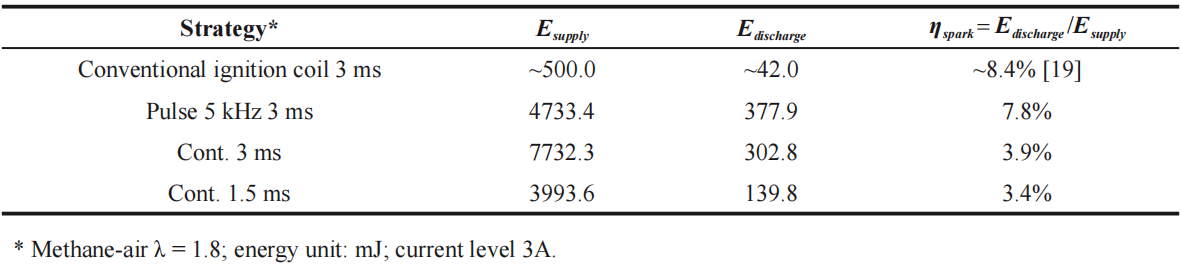
With a duty cycle of 50%, the energy supplied by the pulsed current boost signal listed in this case is said to be equivalent to that of a continuous current boost having a discharge duration of 1.5 ms. Moreover, when utilizing the identical current boost strategy, the efficiency of the spark energy is minimally affected by the duration of the discharge duration.
3.4. Flame Propagation of Lean Combustion via High-Frequency Pulsed Current Boost
To explore the proposed pulsed current boost strategy's effect on lean combustion, the propagation of flames is demonstrated through the implementation of three ignition strategies enumerated in Table 1.
The results of the study presented in Figure 13 indicate that an increase in discharge duration results in a higher release of energy to the mixture. As per the analyses of the high-speed images, the implementation of an ignition strategy, which releases greater levels of discharge energy, appears to prompt a swifter flame propagation and a larger flame zone. The present study indicates that the application of pulsed and continuous current boosts with a discharge duration of 3 ms leads to comparable energy release and combustion performance. However, the energy efficiency of the pulsed current boost is observed to be twice that of the continuous current boost.
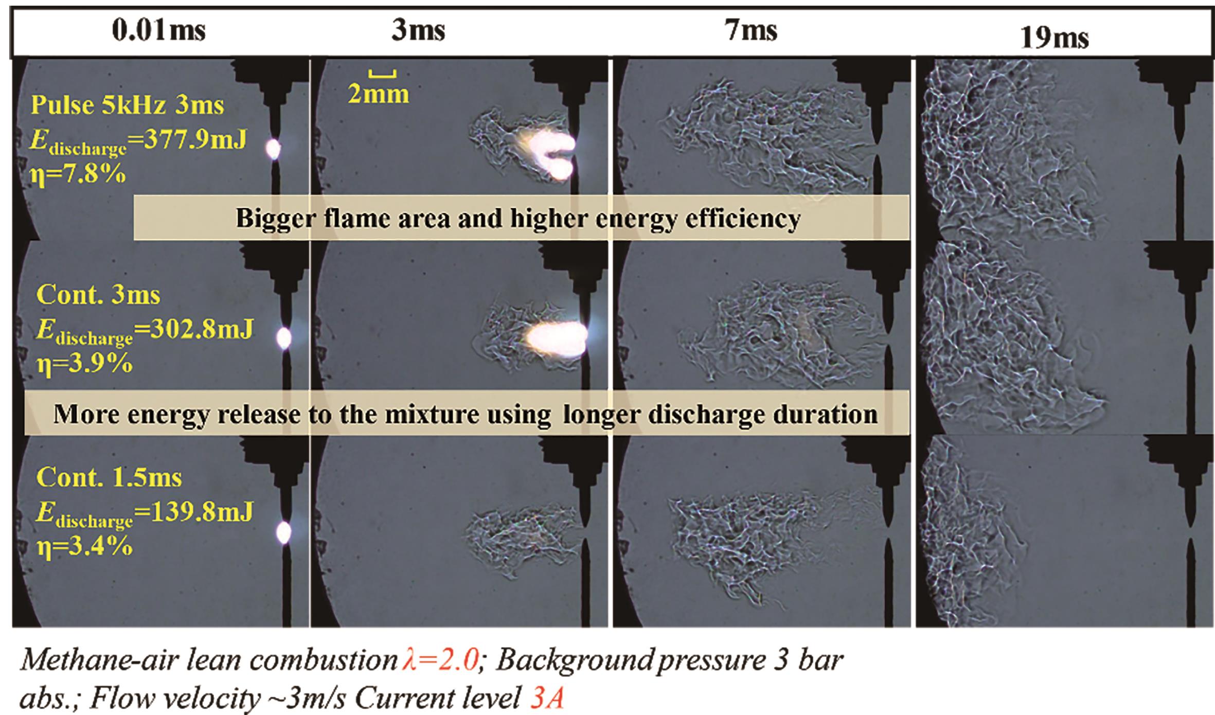
Figure 13. Flame propagation using different current boost strategies.
4. Conclusions
This study proposes a novel high-frequency pulsed current boost strategy of up to 3 A and 20 kHz. Synchronized electrical and optical measurements are conducted for plasma behavior and flame propagation under lean conditions. The major conclusions are:
(1) The application of a high-frequency pulsed current boost strategy has been observed to enhance plasma stretching and reestablishment, owing to its notable impact on plasma stability improvement. The pulsed discharge strategy has been found to accomplish plasma reestablishment without interruption of the plasma stretching process.
(2) In contrast to spark discharge with a continuous current, the utilization of pulsed current boost strategy results in elevated discharge energy through the occurrence of transient high voltage, high power, and high plasma resistance.
(3) The high-frequency pulsed current boost strategy can be improved by manipulating the pulse frequency and current level to further stabilize the plasma stretching and re-establishment.
(4) The utilization of a pulsed current boost strategy results in a reduced requirement for supply energy when compared to continuous current discharge, consequently leading to a better spark energy efficiency.
(5) Given a constant duration of discharge, the usage of a pulsed current boost strategy has been observed to yield a reduction in energy consumption of the ignition system, without compromising on the combustion performance.
Author Contributions: Conceptualization, M. Z. and X. Y.; methodology, X. Y. and L. W.; software, L. W. and S. L.; validation, L.W. and Z.Y.O.; formal analysis, L.W. and Z.Y.O.; investigation, L.W.; resources, L.W.; data curation, L.W. and X.Y.; writing—original draft preparation, L.W.; writing—review and editing, L.W. and Z.Y.O.; visualization, L.W.; supervision, X.Y. and M.Z.; project administration, M.Z.; funding acquisition, M.Z. All authors have read and agreed to the published version of the manuscript.
Funding: This research received no external funding
Data Availability Statement: Not applicable.
Acknowledgments: The research at the Clean Combustion Engine Laboratory is partially sponsored by: Natural Sciences and Engineering Research Council of Canada (NSERC) —Industrial Research Chairs Grants (IRC), Collaborative Research and Development Grants (CRD), Research Tools and Instruments grants program (RTI), Discovery Grants (individual) program (DG); Canada Foundation for Innovation (CFI) —Ontario Research Foundation (ORF); and the University of Windsor. Special thanks to Torch and other Original equipment manufacturers (OEMs) for their technical support, and Clean Combustion Engine Lab (CCEL) colleagues’ contribution in their time.
Conflicts of Interest: The authors declare no conflict of interest.
References
- Yu, X.; Sandhu, N.S.; Yang, Z.; et al. Suitability of Energy Sources for Automotive Application – A Review. Applied Energy 2020, 271, 115169. DOI: https://doi.org/10.1016/j.apenergy.2020.115169
- O’Connor, J.; Borz, M.; Ruth, D.; et al. Optimization of an Advanced Combustion Strategy Towards 55% BTE for the Volvo SuperTruck Program. SAE International Journal of Engines 2017, 10(3), 1217–1227. DOI: https://doi.org/10.4271/2017-01-0723
- Liu, Z. Alternative Fuels in Automotive Vehicles. International Journal of Automotive Manufacturing and Materials 2023, 2(1), 7. DOI: https://doi.org/10.53941/ijamm0201007
- Fu, J.; Zhu, G.; Zhou, F.; et al. Experimental Investigation on the Influences of Exhaust Gas Recirculation Coupling with Intake Tumble on Gasoline Engine Economy and Emission Performance. Energy Conversion and Management 2016, 127, 424–436. DOI: https://doi.org/10.1016/j.enconman.2016.09.033
- Hosseini, V.; Neill, W.; Thomson, K.; et al. Effect of Initial and Operating Conditions on Soot Emissions from an HCCI Engine. In Proceedings of Combustion Institute/Canadian Section, Spring Technical Meeting, Montreal, Quebec, Canada, 2009, pp. 151–157.
- Alkidas, A.C. Combustion Advancements in Gasoline Engines. Energy Conversion and Management 2007, 48(11), 2751–2761. DOI: https://doi.org/10.1016/j.enconman.2007.07.027
- Schneider, A.; Leick, P.; Hettinger, A.; et al. Experimental Studies on Spark Stability in an Optical Combustion Vessel under Flowing Conditions. In Internationaler Motorenkongress 2016: Mit Konferenz Nfz-Motorentechnologie. J. Liebl, and C. Beidl, eds., Springer Fachmedien, Wiesbaden, Germany, 2016, pp. 327–348. DOI: https://doi.org/10.1007/978-3-658-12918-7_22
- Yang, Z.; Yu, X.; Yu, S.; et al. Impacts of Spark Discharge Current and Duration on Flame Development of Lean Mixtures Under Flow Conditions. In Proceedings of the ASME 2018 Internal Combustion Engine Division Fall Technical Conference. Volume 1: Large Bore Engines; Fuels; Advanced Combustion, American Society of Mechanical Engineers, San Diego, California, USA, 4–7 November, 2018, p. V001T03A032. DOI: https://doi.org/10.1115/ICEF2018-9771
- Wang, L.; Yu, X.; Jin, L.; et al. Impact of Plasma Stretch on Spark Energy Release Rate under Flow Conditions. SAE Technical Paper 2022, No. 2022–01–0438. SAE International, Warrendale, PA, USA. DOI: https://doi.org/10.4271/2022-01-0438
- Shiraishi, T.; Teraji, A.; Moriyoshi Y. The Effects of Ignition Environment and Discharge Waveform Characteristics on Spark Channel Formation and Relationship between the Discharge Parameters and the EGR Combustion Limit. SAE International Journal of Engines 2016, 9(1), 171–178. DOI: https://doi.org/10.4271/2015-01-1895
- Yu, X.; Yang, Z.; Yu, S.; et al. Discharge Characteristics of Current Boosted Spark Events Under Flow Conditions. In Internal Combustion Engine Division Fall Technical Conference. American Society of Mechanical Engineers: New York, NY, USA. 2017, Vol. 58318, p. V001T03A017. DOI: https://doi.org/10.1115/ICEF2017-3657
- Zhu, X.; Sforza, L.; Ranadive, T.; et al. Experimental and Numerical Study of Flame Kernel Formation Processes of Propane-Air Mixture in a Pressurized Combustion Vessel. SAE International Journal of Engines 2016, 9(3), 1494–1511. DOI: https://doi.org/10.4271/2016-01-0696
- Sayama, S.; Kinoshita, M.; Mandokoro, Y.; et al. Spark Ignition and Early Flame Development of Lean Mixtures under High-Velocity Flow Conditions: An Experimental Study. International Journal of Engine Research 2019, 20(2), 236–246. DOI: https://doi.org/10.1177/1468087417748517
- Wang, L.; Chen, G.; Tjong, J.; et al. Electrical and Optical Characterization Methodologies for Advanced Spark Ignition. Journal of Energy Resources Technology 2022, 144(9), 092104. DOI: https://doi.org/10.1115/1.4053437
- Soldera, F. A.; Mucklich, F. T.; Hrastnik, K.; et al. Description of the Discharge Process in Spark Plugs and Its Correlation with the Electrode Erosion Patterns. IEEE Transactions on Vehicular Technology 2004, 53(4), 1257–1265. DOI: https://doi.org/10.1109/TVT.2004.830977
- Donaldson, A.; Kristiansen, M.; Watson, A.; et al. Electrode Erosion in High Current, High Energy Transient Arcs. IEEE Transactions on Magnetics 1986, 22(6), 1441–1447. DOI: https://doi.org/10.1109/TMAG.1986.1064638
- Huang, S.; Li, T.; Zhang, Z.; et al. Influencing Factors on the Vibrational and Rotational Temperatures in the Spark Discharge Channel. Energy 2021, 222, 119995. DOI: https://doi.org/10.1016/j.energy.2021.119995
- Yang, Z.; Wang, L.; Sandhu, N.S.; et al. Discharge Current Management for Diluted Combustion under Forced Flow Conditions. SAE Technical Paper 2020, No. 2020-01–1118. SAE International, Warrendale, PA, USA. DOI: https://doi.org/10.4271/2020-01-1118
- Yu, X.; Yu, S.; Yang, Z.; et al. Improvement on Energy Efficiency of the Spark Ignition System. SAE Technical Paper 2017, No. 2017-01–0678. SAE International, Warrendale, PA, USA. DOI: https://doi.org/10.4271/2017-01-0678


