

Downloads
Download


This work is licensed under a Creative Commons Attribution 4.0 International License.
Article
Macroscopic and Microscopic Characteristics of a GDI Spray Under Various Thermodynamic Conditions
Jian Li 1, Lulu Li 1, Rujie Xiao 1, Yuanfei Liang 1, Shuyi Qiu 2, and Xuesong Li 2,*
1 SAIC GM Wuling Automobile Co., Ltd., 18 Hexi Rd, Liunan District, Liuzhou 545001, China
2 School of Mechanical Engineering, Shanghai Jiao Tong University, 800 Dongchuan Road, Shanghai 200240, China
* Correspondence: xuesonl@sjtu.edu.cn
Received: 3 April 2023
Accepted: 9 August 2023
Published: 28 August 2023
Abstract: Gasoline direct injection (GDI) is the most common and advanced fuel supply strategy for gasoline engines. The fuel atomization quality and fuel/air mix degree determine the subsequent combustion efficiency and emissions. However, the engine works in complex conditions which have numerous thermodynamic boundary conditions, and the characteristics of fuel atomization also change accordingly. It is necessary to clarify the influence of various thermodynamic conditions on the GDI spray. In this work, three different types of optics diagnostic methods were utilized to capture the macroscopic and microscopic characteristics of a commercial GDI injector spray under various thermodynamic boundary conditions. Specifically, Mie-scattering photography was employed to get the macroscopic parameters; planar Mie-scattering photography was utilized to get the spray pattern; phase Doppler interferometry (PDI) was used to get the microscopic characteristic, i.e., the droplet size distributions. It is found from this study that higher injection pressure, lower ambient pressure, and lower ambient temperature would lead to longer penetration and larger plume width. Lower ambient pressure and higher ambient temperature would cause a smaller spray pattern. Higher injection pressure, lower ambient pressure, and higher ambient temperature would result in smaller droplet sizes.
Keywords:
internal combustion engine gasoline direct injection optics diagnostic fuel spray thermodynamic condition1. Introduction
In the context of “carbon neutrality”, combined with the use of zero-carbon fuels, the internal combustion (IC) engine will still be the mainstream power machine for a long time. With the continuous tightening of fuel consumption and emission regulations, the hybrid system has received more attention in recent years. With the cooperation of the electric motor, the IC engine can work in specific regions, which corresponds to higher thermal efficiency and low emissions. The characteristics of working in specific conditions make it possible to precisely control the spray in the cylinder. Good atomization of the spray and achieving a combustible fuel-air mixture are crucial for subsequent efficient combustion and low emissions. Improper spray always causes the spay wall impingement, resulting in the fuel film deposited in the wall [1‒4]. This can significantly deteriorate the combustion and emission performance.
Optics diagnostic has the feature of being non-invasive and the ability to obtain transient flow field characteristics, which is suitable for high turbulence spray measurement. Qiu et al. [1] utilized the high-speed Mie-scattering photography to measure free sprays and impinged sprays. Mie-scattering photography is capable of revealing the spray’s macroscopic features under various boundary conditions. Wu et al. [5] used planar high-speed Mie-scattering photography to measure the spray pattern, and the spray pattern at the specific location was captured. Besides, the plume-to-plume interactions were easier to be revealed using the planar photography method. Phase Doppler interferometry (PDI) is a well-established optical diagnostic method for droplet size measurement. It uses the relationship between the interference fringe properties and droplet diameter to measure the droplet size. Guo et al. [6] first utilized PDI to measure the droplet size in the optical engine. As a well-established droplet size measurement method, PDI can also be used for the development and validation of novel diagnostics methods. For instance, Qiu et al. [7] used PDI to calibrate and verify the self-developed SLIPI-LIEF/Mie method, which is a novel planar droplet sizing technique.
Due to the GDI engine’s characteristics of directly injecting fuel into the cylinder, the boundary conditions of the injection will be affected by the ambient conditions in the cylinder. In addition, the choice of injection pressure is also critical for atomization. Hence, there is already much research on the influence of different boundary conditions on the spray characteristic of IC engines. Chan et al. [8] investigated the effect of injection pressure on spray, and it was found that increasing injection pressure enhances the fuel vaporization of flash-boiling spray. Du et al. [9] investigated the effects of injection pressure on spray structure, and it revealed the spray structure after spray wall impingements, which includes the liquid phase impingement spray radius, liquid-phase impingement spray height, etc. Li et al. [10] investigated the influence of fuel temperature on the macroscopic characteristic of the spray plume. It indicated the increased fuel temperature would cause more intense plume expansion. Wu et al. [11,12] investigated the influence of ambient pressure on macroscopic features and patterns. It was found that lower ambient pressure increases the inner bubble size and volume fraction, which led to a narrower liquid core of the near-nozzle fuel jet.
However, the investigation of spray features is almost limited to a single region, i.e., only analysis of single spray feature, like the spray penetration, droplet size, etc. Besides, systematic macroscopic and microscopic characteristic research under various boundary conditions is lacking. Most existing studies have focused only on the influence of a single boundary condition, such as injection pressure [13] and ambient pressure [14], etc. This work combined three different optics diagnostic methods to measure the macroscopic and microscopic characteristics of spray under a large range of thermodynamic conditions, in order to reveal the influence of thermodynamic boundary conditions on spray characteristics.
2. Methods
In this investigation, we examine the spray produced by a commercial 5-hole gasoline direct injection (GDI) injector, which was used in commercial GDI engines. The nozzle diameter is 150 µm. The static flow rate at 10 MPa injection pressure is 328.5 g/min. The static flow rate is the rate of fuel delivered by an injector when energized in the fully opened position. Referring to the Society of Automotive Engineers (SAE) J2715 proposed by the SAE Gasoline Fuel Injection Standards Committee, n-heptane was used for the measurement since it represents the main component of gasoline. Figure 1 depicts all of the experimental setups used in this investigation. This investigation utilized three separate measurements, including Mie scattering photography, planar Mie scattering photography, and PDI, respectively. The experimental setups share a similar high-temperature, high-pressure (HTHP) constant volume chamber but are different in their optical diagnostics setups. As seen in Figure 1, the chamber temperature and pressure can be controlled by external systems. The ambient gas was nitrogen, and the pressure was either regulated by external high-pressure nitrogen cylinders or reduced by a vacuum pump connected to the chamber. To achieve different thermodynamic conditions, external electrical heating was utilized to heat the ambient air to the desired temperatures. In the setup for Mie scattering measurement as shown in panel (a) of Figure 1, a matrix LED lamp was adopted to illuminate the fuel spray. Meanwhile, the incident light scattered as hitting the spray and scattering light was captured by a high-speed camera. In the setup for planar Mie scattering measurement in panel (b) of Figure 1, the 527 nm high-speed Nd: YLF laser was utilized, combined with the cylindrical mirror, which could produce a 1 mm thick, 100 mm height laser sheet at 50 mm plane (i.e., along the axis of the injector, a plane that at a distance of 50 mm from the nozzle tip). While the laser sheet illuminated the spray droplets, the Mie scattering light was captured by a high-speed camera. To provide a clearer visualization of the setup, Planar (a) and (b) also depict the actual measurement configurations from a top-view perspective. In the Mie scattering measurement, the injector's electrical connector is oriented vertically towards the camera. In the planar Mie scattering measurement, the injector's electrical connector is aligned parallel to the direction of the incident laser beam. Panel (c) of Figure 1 depictured the setup of PDI measurement. PDI measures the size of droplets utilizing the principles of interferometry. By analyzing the interference pattern, PDI measures the phase difference between the scattered light waves from different droplets. This phase difference corresponds to the droplet's position within the intersection region and can be used to determine its size. The transmitter of the PDI device generates the interference laser, which overlaps at the measurement location. When the droplet went through the measurement location, the scattering light, which contains the droplet size information, would be captured by the PDI receiver. The droplet size information would be revealed after the signal processing.
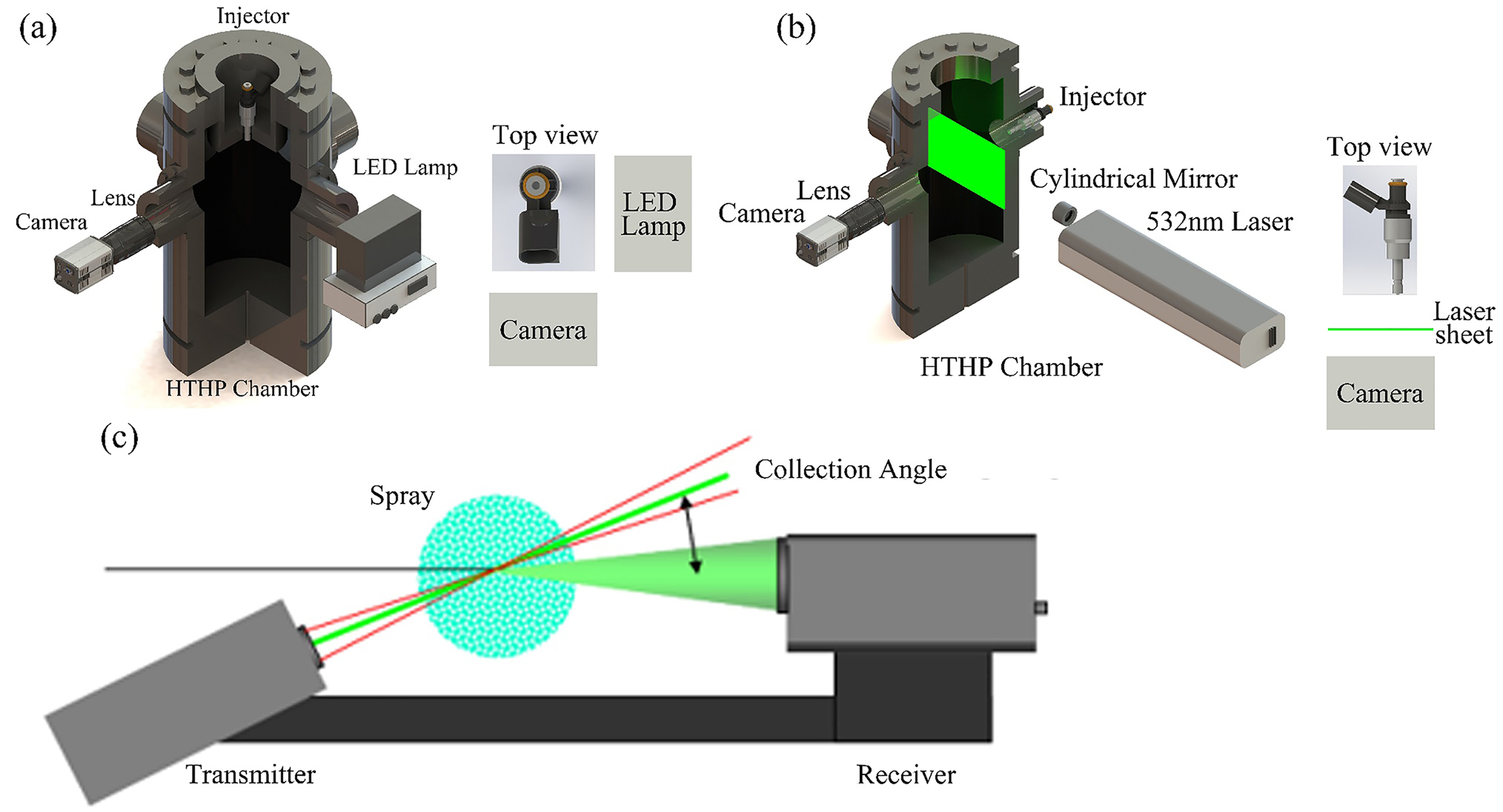
Figure 1. Experimental setup. (a) Mie-scattering photography measurement; (b) Planar Mie-scattering photography measurement; (c) PDI measurement.
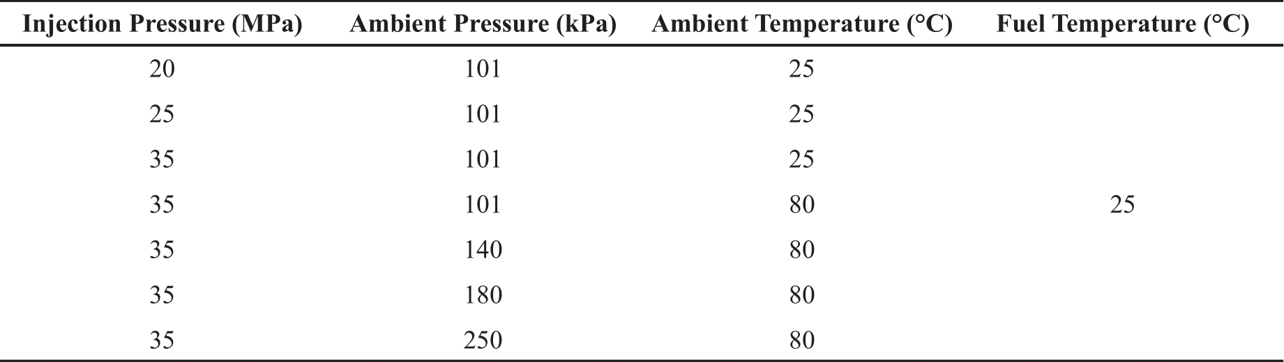
To achieve large-range thermodynamic conditions, various boundary parameters were chosen for the measurement, including the injection pressure, the ambient pressure, and the ambient temperature. Table 1 shows the test conditions used in this work. The injection pressure ranged from 20 MPa to 35 MPa, the ambient pressure ranged from 101 kPa to 250 kPa, and the ambient temperature was either 25°C or 80°C. The injection duration was fixed to 1.5 ms. All the selected conditions fall within the thermodynamic range of actual commercial internal combustion (IC) engines [15]. Regarding the repetitions, the Mie-scattering and planar Mie-scattering tests were repeated 15 times for each condition. Five thousand valid particles were collected for each condition in terms of PDI measurement.
Table 1. Test conditions used in this work.
3. Results and Discussions
3.1. Influence of Injection Pressure
Injection pressure is a critical parameter for the GDI powertrain. Nowadays, the development tendency is to pursue higher injection pressure. This shows the necessity to investigate the influence of injection pressure on fuel spray. Figure 2 shows the macroscopic and microscopic measurement results under different fuel injection pressures. Panel (a) of Figure 2 shows the spray imaging results using Mie scattering photography method. The measurement timing was 1 ms after the start of injection (ASOI). As shown in the picture, the spray penetration increases with the increment of fuel injection pressure. It is reasonable since the larger injection pressure leads to a larger initial droplet velocity, which would cause longer penetration. Penetration is defined as the farthest distance along the injector's axis from the spray's front edge to the injector's tip [16]. Besides, the spray width increased with the increment of fuel injection pressure. Spray width refers to the transverse dimension of a liquid spray pattern. It represents the horizontal extent of the spray in a specific direction perpendicular to the injector's axis. It is also reasonable since the orientation of the injector hole is not straight down, and the initial droplet velocity has the radial component, which would increase with the increment of fuel pressure. The increased radial velocity would lead to larger spray width. Panel (b) of Figure 2 demonstrates the spray pattern results at 1 ms ASOI using the planar Mie scattering photography method at 50 mm plane. The tendency of spray pattern characteristics was hard to summarize. With an injection pressure of 20 MPa, the spray pattern area was the smallest, where the spray pattern area refers to the total area of all plumes’ patterns. When the injection pressure was raised, the spray pattern area increased. However, the largest spray pattern area was produced at 25 MPa injection pressure instead of at 35 MPa injection pressure. In addition, the plume merged only at 25 MPa injection pressure. The largest spray pattern area at 25 MPa was attributed to plume-to-plume interaction, which occurs exclusively in this condition. It is believed that the increased radial velocity and not-too-fast vertical velocity contributed to this phenomenon. As for the 20 MPa injection pressure condition, the radial velocity was not large enough, so the plume’s radial expansion distance was not large enough for the plume-to-plume interaction. As for the 35 MPa condition, the vertical velocity was too large, so there wasn’t enough time for the plume to radial expand and merge subsequently. Panel (c) of Figure 2 showes the droplet size histogram and cumulative volume curve using the PDI method. Besides, the commonly used droplet statistic parameters were shown in each picture. It was obvious that the increased injection pressure caused a smaller droplet size, and the Sauter mean diameter (SMD) reduced with the increment of injection pressure. Indeed, under various injection pressures, the droplet size distribution exhibits a similar unimodal distribution. Upon careful observation of Panel (c), it becomes apparent that the peak droplet size decreases with increasing injection pressure. It is widely proven that the increased injection pressure could reduce droplet sizes. However, the degree of droplet size reduction by increasing injection pressure is insignificant when the injection pressure is already high (approximately larger than 35 MPa). Besides, the cost of a high-pressure fuel supply system is commonly high. The commercial GDI system should consider the trade-off between the cost of a high-pressure fuel supply system and the droplet size.
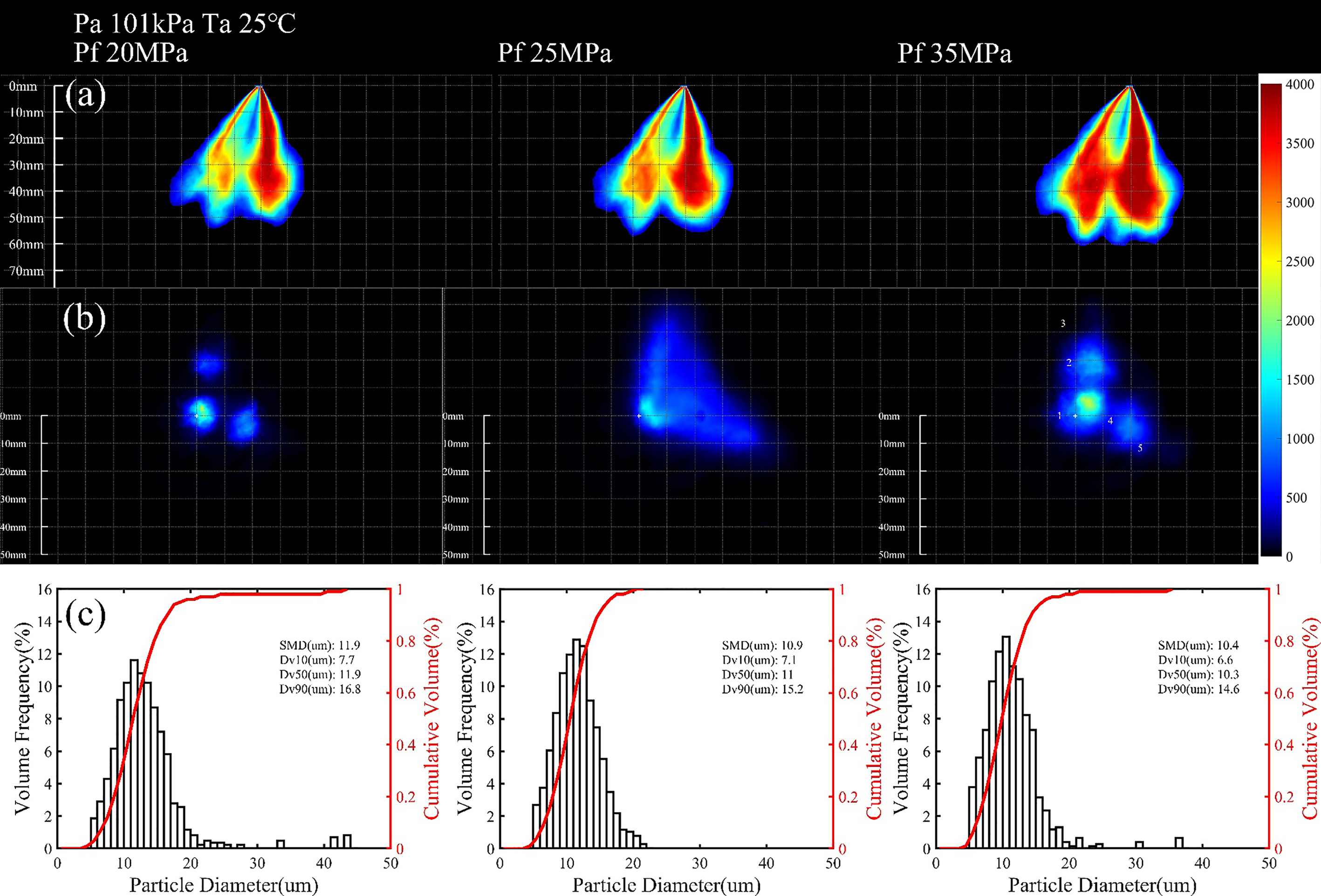
Figure 2. Macroscopic and microscopic measurement results. Different fuel injection pressures were chosen. (a) Spray imaging results using Mie scattering photography method; (b) Spray pattern results using the planar Mie scattering photography method; (c) Droplet size results using the PDI method.
3.2. Influence of Ambient Pressure
Differing from the injection pressure which is determined by the powertrain system and usually fixed in one specific engine, the ambient pressure was much more changeable for the complicated engine conditions. Revealing the influence of ambient pressure on the spray was favorable for formulating the injection strategy. Figure 3 shows the macroscopic and microscopic measurement results under different ambient pressures. Panel (a) of Figure 3 showes spray imaging at 1.2 ms ASOI. It is worth noting that the measurement timing was 1.2 ms ASOI instead of 1 ms ASOI. Due to the increased resistance to spray development under high ambient pressure, it takes longer for the spray to reach the 50 mm plane. Therefore, 1.2 ms ASOI was chosen as it allows sufficient time for the spray to reach the 50 mm plane. The penetration reduced as the ambient pressure increased. It is predictable since the large ambient pressure would cause larger resistance for spray propagation. The influence on radial spray expansion of ambient pressure is less significant, for the initial radial speed was smaller than the initial axial speed. Panel (b) of Figure 3 illustrates the spray pattern under different ambient pressures at 1.2 ms ASOI. The radial plume expansion was more obvious in this view, which also indicates the necessity to apply multiple diagnostic methods. As shown in panel (b), a larger ambient pressure results in a smaller pattern area, which was caused by the higher resistance under higher ambient pressure conditions. The phenomenon that high ambient pressure impedes the expansion of the liquid phase spray has also been reported in previous studies on single-plume spray [10]. Panel (c) of Figure 3 illustrates the Droplet size histogram and cumulative volume curve using the PDI method. In general, the droplet size increased as the ambient pressure increased. There are three reasons for this phenomenon. Firstly, the increased ambient pressure reduces the droplet velocity, and the higher ambient pressure hindered the propagation of both the spray liquid phase and spray vapor phase [17,18]. These make it hard to break up by aerodynamic force for the intensity of the interaction between spray and ambient gas is weakened. Secondly, the high ambient pressure results in lower superheat degree, which is a criterion for phase change spray. Lower superheat degree of spray causes lower atomization efficiency, reflecting larger droplet size [19].
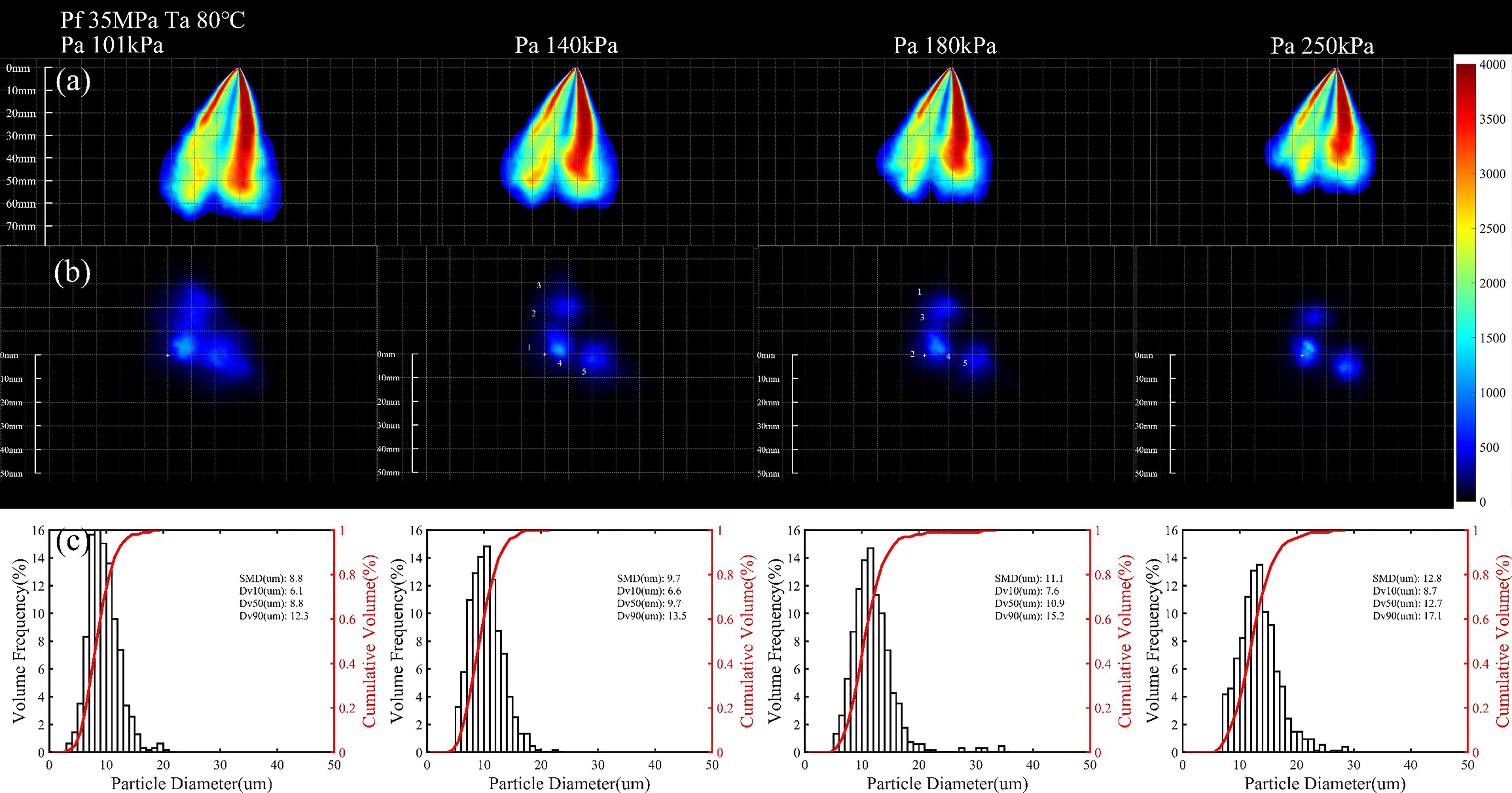
Figure 3. Macroscopic and microscopic measurement results. Different fuel ambient pressures were chosen. (a) Spray imaging results using Mie scattering photography method; (b) Spray pattern results using the planar Mie scattering photography method; (c) Droplet size results using the PDI method.
3.3. Influence of Ambient Temperature
Similar to ambient pressure discussed in the above section, ambient temperature is also determined by engine operation conditions. The main purpose of ambient temperature investigation was to figure out the spray difference between cold start and warm conditions, which was helpful in optimizing fuel injection strategy. Panel (a) of Figure 4 shows the spray image at 1 ms ASOI. Since the optics setup is the same, the intensity could qualitatively represent the spray droplet number density. Evidently, higher ambient temperature caused lower droplet number density. The evaporation of droplets led to this phenomenon. Similar results are shown in panel (b) of Figure 4. Spray pattern measurement results at 1 ms ASOI showed that the higher ambient temperature resulted in a smaller and sparser spray, which is reasonable and understandable as higher ambient temperature leads to more intense evaporation, resulting in a decrease in droplets size, thereby leading to a smaller spray pattern area. Panel (c) of Figure 4 shows the droplet size measurement results. Higher ambient temperature causes smaller droplets. And the number of large droplets (diameter larger than 20 µm) reduced significantly. The results shown above indicate that the warm condition (ambient temperature of 80°C) was beneficial for the spray atomization and formation of a combustible mixture. Conversely, the atomization quality under cold start conditions where the ambient temperature was about 25°C was bad, which should be emphasized during the design of the injection system. Improving the engine heat speed is a potential solution to the problem.
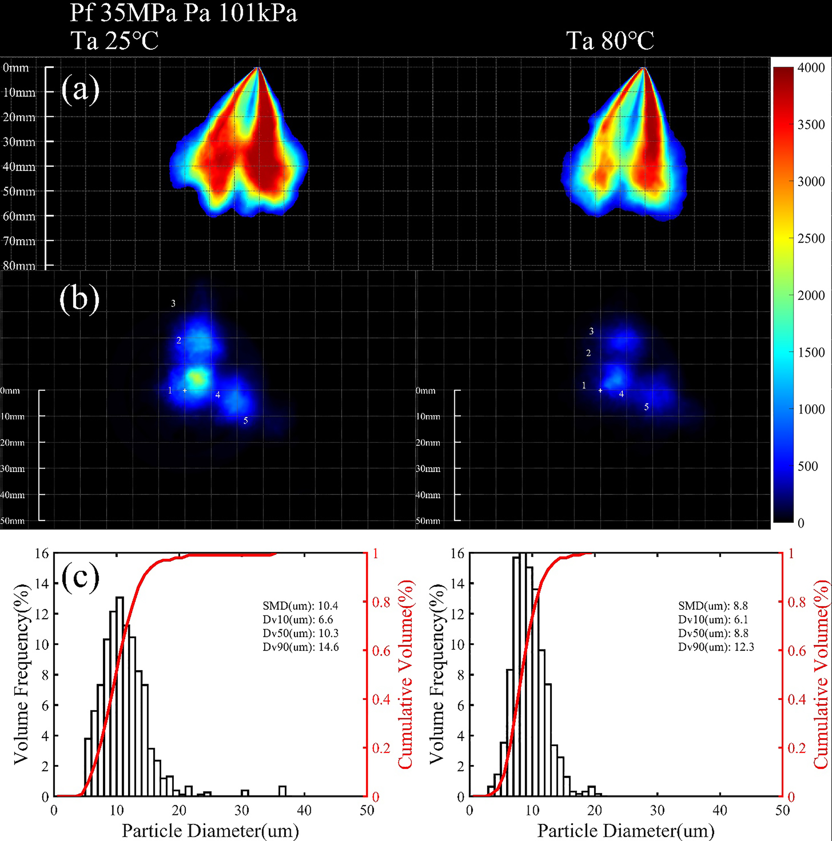
Figure 4. Macroscopic and microscopic measurement results. Different fuel ambient temperatures were chosen. (a) Spray imaging results using Mie scattering photography method; (b) Spray pattern results using the planar Mie scattering photography method; (c) Droplet size results using the PDI method.
4. Conclusions
In this work, we explored the macroscopic and microscopic characteristics of a commercial GDI injector spray with three different optical diagnostic methods. Specifically, the Mie scattering photography was utilized to get the macroscopic spray image; the planar Mie scattering photography was used to capture the spray pattern; the PDI method was used to get the droplet size distribution. The influence on spray characteristics of different thermodynamic conditions was analyzed, and the following conclusions can be made:
- Higher injection pressure would lead to longer penetration and larger spray width. The droplet size was reduced with the increment of injection pressure. However, the degree of droplet size reduction by increasing injection pressure is insignificant when the injection pressure is already high. It is worth giving a trade-off between the improved atomization efficiency and raised cost caused by applying higher injection pressure.
- Larger ambient pressure would cause shorter penetration and smaller plume width. The droplet size reduces with the increment of ambient pressure. Lower velocity, a higher concentration of fuel liquid and vapor phase, and lower superheat degree were the reason for larger droplet size under higher ambient conditions.
- Under higher ambient temperature conditions, the spray has shorter penetration and becomes sparser. The reason for this phenomenon is more intense evaporation under higher ambient temperature conditions. Under cold start conditions, i.e., low ambient temperature conditions, longer penetration, and worse atomization should be emphasized.
Author Contributions: Conceptualization, J.L. and L.L.; methodology, R.X. and Y.L.; software, S.Q.; validation, S.Q.; formal analysis, X.L.; investigation, J.L.; resources, J.L.; data curation, R.X. and J.L.; writing—original draft preparation, L.; writing—review and editing, X. L.; visualization, Y. L.; supervision, X. L.; project administration, X. L.; funding acquisition, X.L.
Funding: This research is funded by the National Natural Science Foundation of China (Grant Numbers E52276125, E52006140).
Data Availability Statement: Data will be made available on request.
Conflicts of Interest: The authors declare no conflict of interest.
References
- Qiu, S.; Xiao, D.; Zhang, X.; et al. Experimental investigations of the phase change impacts on flash boiling spray propagations and impingements. Fuel 2022, 312, 122871. DOI: https://doi.org/10.1016/j.fuel.2021.122871
- Xiao, D.; Qiu, S.; Hung, D.; et al. Evaporation and condensation of flash boiling sprays impinging on a cold surface. Fuel 2021, 287, 119423. DOI: https://doi.org/10.1016/j.fuel.2020.119423
- Zhang, G.; Shi, P.; Luo, H.; et al. Investigation on fuel adhesion characteristics of wall-impingement spray under cross-flow conditions. Fuel 2022, 320, 123925. DOI: https://doi.org/10.1016/j.fuel.2022.123925
- Zhang, G.; Si, Z.; Zhai, C.; et al. Characteristics of wall-jet vortex development during fuel spray impinging on flat-wall under cross-flow conditions. Fuel 2022, 317, 123507. DOI: https://doi.org/10.1016/j.fuel.2022.123507
- Wu, S.; Yang, S.; Wooldridge, M.; et al. Experimental study of the spray collapse process of multi-hole gasoline fuel injection at flash boiling conditions. Fuel 2019, 242, 109–123. DOI: https://doi.org/10.1016/j.fuel.2019.01.027
- Guo, H.; Ma, X.; Li, Y.; et al. Effect of flash boiling on microscopic and macroscopic spray characteristics in optical GDI engine. Fuel 2017, 190, 79–89. DOI: https://doi.org/10.1016/j.fuel.2016.11.043
- Qiu, S.; Wang, S.; Zhang, Y.; et al. Dense-field spray droplet size quantification of flashing boiling atomization using structured laser illumination planar imaging technique. Fuel 2023, 335, 127085. DOI: https://doi.org/10.1016/j.fuel.2022.127085
- Chan, Q.N.; Bao, Y.; Kook S. Effects of injection pressure on the structural transformation of flash-boiling sprays of gasoline and ethanol in a spark-ignition direct-injection (SIDI) engine. Fuel 2014, 130, 228–240. DOI: https://doi.org/10.1016/j.fuel.2014.04.015
- Du, W.; Zhang, Q.; Bao, W.; et al. Effects of injection pressure on spray structure after wall impingement. Applied Thermal Engineering 2018, 129, 1212–1218. DOI: https://doi.org/10.1016/j.applthermaleng.2017.10.083
- Li, X.; Xu, Q.; Qiu, S.; et al. Investigations on the impact of phase change on single plume flash boiling radial expansion and drop-sizing characteristics. Applied Thermal Engineering 2022, 202, 117911. DOI: https://doi.org/10.1016/j.applthermaleng.2021.117911
- Wu, S.; Xu, M.; Hung, D. L.; et al. Near-nozzle spray and spray collapse characteristics of spark-ignition direct-injection fuel injectors under sub-cooled and superheated conditions. Fuel 2016, 183, 322–334. DOI: https://doi.org/10.1016/j.fuel.2016.06.080
- Wu, S.; Xu, M.; Hung, D. L.; et al. In-nozzle flow investigation of flash boiling fuel sprays. Applied Thermal Engineering 2017, 117, 644–651. DOI: https://doi.org/10.1016/j.applthermaleng.2016.12.105
- Su, T.F.; Chang, C.T.; Reitz, R.D.; et al. Effects of injection pressure and nozzle geometry on spray SMD and DI emissions. SAE transactions 1995, 975–984. DOI: https://doi.org/10.4271/952360
- Roisman, I. V.; Araneo, L.; Tropea C. Effect of ambient pressure on penetration of a diesel spray. International Journal of Multiphase Flow 2007, 33(8), 904–920. DOI: https://doi.org/10.1016/j.ijmultiphaseflow.2007.01.004
- Guo, H.; Ding, H.; Li, Y.; et al. Comparison of spray collapses at elevated ambient pressure and flash boiling conditions using multi-hole gasoline direct injector. Fuel 2017, 199, 125–134. DOI: https://doi.org/10.1016/j.fuel.2017.02.071
- Hung, D.L.; Harrington, D.L.; Gandhi, A.H.; et al. Gasoline fuel injector spray measurement and characterization–a new SAE J2715 recommended practice. SAE International Journal of Fuels and Lubricants 2009, 1(1), 534–548. DOI: https://doi.org/10.4271/2008-01-1068
- Zeng, W.; Xu, M.; Zhang, G.; et al. Atomization and vaporization for flash-boiling multi-hole sprays with alcohol fuels. Fuel 2012, 95, 287–297. DOI: https://doi.org/10.1016/j.fuel.2011.08.048
- Zhang, G.; Xu, M.; Zhang, Y.; et al. Quantitative measurements of liquid and vapor distributions in flash boiling fuel sprays using planar laser induced exciplex technique. SAE Technical Paper 2011, No. 2011-01-1879. DOI: https://doi.org/10.4271/2011-01-1879
- Xu, M.; Zhang, Y.; Zeng, W.; et al. Flash Boiling: Easy and Better Way to Generate Ideal Sprays than the High Injection Pressure. SAE International Journal of Fuels and Lubricants 2013, 6(1), 137–148. DOI: https://doi.org/10.4271/2013-01-1614


