

Downloads
Download


This work is licensed under a Creative Commons Attribution 4.0 International License.
Article
Advances and Challenges in Combustion Control of Radio Frequency Oscillating Plasma Discharge
Linyan Wang , Xiao Yu , Graham Reader , and Ming Zheng *
Department of Mechanical, Automotive and Materials Engineering, University of Windsor, 401 Sunset Avenue, Windsor, N9B 3P4 Ontario, Canada
* Correspondence: mzheng@uwindsor.ca
Received: 18 July 2023
Accepted: 13 September 2023
Published: 20 September 2023
Abstract: Oscillating plasma (corona) ignition is a promising technique for producing a larger initial ignition volume for achieving cleaner combustion. The oscillating plasma system provides a quick response to the ignition command compared with the conventional transistor-coil-ignition systems (TCI). Subsequently, the shorter combustion duration contributes to further improvement of engine efficiency under lean/diluted conditions. The challenges of oscillating plasma ignition appear under elevated background pressures, mostly owing to fewer plasma streamers and even void discharge, thus the advantage of oscillating plasma discharge over spark discharge is compromised. To suffice the industrial applications, the challenges of plasma generation and control platforms are investigated and discussed in this work. The challenges include ignition control, background condition impacts, and other external disturbances. A flexible modulation for oscillating plasma generation is established, with the measurements of discharge voltage and current. High-speed imaging, simultaneous with electrical waveform measurements is applied to record the plasma formation and flame propagation. This research provides advances in the ignition control for the oscillating plasma discharge, adding a foundation and reference for the oscillating plasma diagnostics under engine-like conditions with variations of pressure, temperature, gas composition, and flow pattern.
Keywords:
oscillating plasma discharge corona discharge ignition control clean combustion1. Introduction
The internal combustion (IC) engine has been the primary power source for automotive applications, and will continuously power the majority of automotive vehicles including hybrids, in the foreseeable future [1‒4]. The greenhouse gas (GHG) emission challenge can only be met optimally with an appropriate technology mix, such as electrical energy, hydrogen or E-fuels, and renewable fuels, adapted to each respective application [5]. To achieve such high efficiencies, lean-burn and exhaust gas recirculation (EGR) diluted combustion technologies need to be adopted to reduce pumping loss under partial load, mitigate knocking events to achieve preferable combustion phasing under high engine load, and reduce heat transfer loss because of the low-temperature combustion [6]. However, ignition difficulty and slow flame propagation speed become the major challenges because of the much lower chemical reactivity of the air-fuel mixtures [7,8]. In this context, advanced ignition technologies based on non-equilibrium plasma discharge become important because they show great potential in combustion, emission control as well as fuel reforming [9].
Radio frequency (RF) oscillating plasma (Corona), dielectric barrier discharge, nanosecond discharge, gliding arc, and microwave have higher electron temperatures [10], and they are more kinetically active owing to the rapid production of active radicals and excited species via electron impact dissociation, excitation, and subsequent energy relaxation [11,12]. The enhancement of ignition using non-equilibrium plasma can be achieved in three aspects. First, the branched plasma streamers have the potential to increase the size of the flame kernel and ignition volume [13]. Second, the high electron energy of the non-equilibrium plasma promotes ion chemistry and generates active radicals and small molecule fuel fragments [9], which has benefits on the ignition process. The residence time of OH is typically below 100 μs, as observed in the nanosecond non-equilibrium plasma ignition experiments conducted by Wu [14], and repetitive discharge is often used for nanosecond pulsed non-equilibrium plasma ignition [15]. In comparison, the RF oscillating plasma ignition can continuously produce non-equilibrium plasma in milliseconds duration to compensate for the decay of previously formed radicals until the success of ignition [16]. Third, as the effect of an electric field on flame propagation has been extensively reported in the past, post-ignition flame propagation can be accelerated due to the ionic wind effect near the ignitor [17].
Oscillating plasma discharge shows promises for the stable and successful ignition of lean and diluted mixtures. As shown in Figure 1, without the ground electrode, the streamers released from the plasma antenna can stretch beyond the size of the conventional spark gap and establish a much bigger ignition volume. The high frequency oscillating electric field generated at the tip of the antenna can force distortion on the flame front. The enhancement of the burning rate and acceleration of the flame kernel growth is contributed by the flame front wrinkles in the shadowgraph image [18].
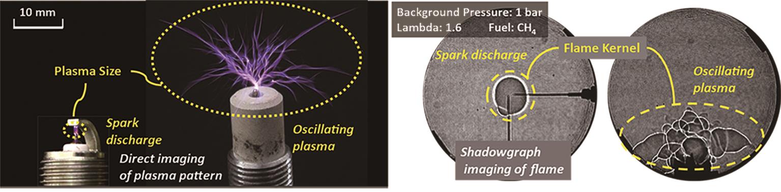
Figure 1. Plasma and conventional spark discharge and relevant flame kernel formation in shadowgraph images (adapted with permission from Yu et al. [19]).
Under engine conditions, the shorter combustion duration contributes to further improvement of engine efficiency under lean/diluted conditions. The oscillating plasma system provides a quick response to the ignition command in microsecond order, compared with millisecond order for a conventional transistor-coil-ignition system (TCI). The system can also continuously deliver ignition energy according to engine demands [10]. Another unique feature of the RF plasma ignition technology is that the combustion chamber, with the working fluid forming a virtual capacitor, is a part of the resonant electrical circuit. This allows potential diagnosis of the flame kernel growth process using the ignition hardware. It is also possible and advantageous to implement electrification near the ignitor to accelerate the flame kernel.
However, as the ground electrode is absent from the plasma antenna, the plasma ignition is susceptible to the surrounding conditions, because the dielectric medium around the plasma antenna becomes a part of the electrical circuit during energy release. An illustrative structural scheme of a basic plasma ignition system is shown in Figure 2. Under engine conditions, the rapid change of in-cylinder pressure and temperature produces a complicated background condition, which challenges a stable plasma discharge [20,21]. At the top dead center (TDC) of engine operation, the distance between the plasma and the surface of the piston is greatly shortened, which can trigger unwanted arc discharge [22,23]. Contamination of the plasma antenna and its ceramic insulator can lead to surface discharge or direct arc to the metal shell of the plasma igniter [23‒25]. Therefore, to ensure robust and reliable plasma discharge, it is essential to understand the discharge mechanism and operational boundaries of the oscillating plasma discharge process [18]. Furthermore, in order to suffice the industrial applications, it is valuable and necessary to discuss the challenges existing in plasma generation and control platforms.
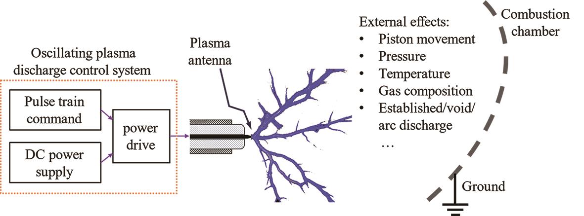
Figure 2. Basic structural scheme of an oscillating plasma ignition system.
In this work, an advanced oscillating plasma discharge control system is proposed, with the discharge process characterized by electrical waveform measurements of the voltage and current. Subsequently, the challenges of plasma discharge under engine-like conditions are discussed in detail. Elevated background pressure can significantly affect the RF oscillating plasma discharge, in terms of fewer streamer numbers and smaller size, which will compromise its advantage over a spark event. The electrical waveforms with the simultaneous high-speed imaging of the visualized plasma streamers and flame propagation present a deeper understanding of the oscillating plasma discharge and ignition. This research adds references for plasma ignition and diagnostics under engine-like conditions with variations in pressure, temperature, gas composition, and flow pattern.
2. RF Oscillating Plasma Discharge and Control System
An in-house built RF oscillating plasma discharge control system has been used to generate oscillating plasma discharge with adjustable discharge frequency, voltage, and duration [16,22]. The system consists of a single-electrode igniter, a resonator coil, an RF transformer, and power drive electronics. The high-frequency (800 kHz‒2.6 MHz) pulse train is generated by a function generator (Agilent 33220A) and should be consistent with the RLC electrical resonance frequency of the ignition system to achieve the highest discharge voltage at the tip of the ignitor. The control command (for discharge duration and frequency control) is generated via an RT-FPGA, i.e., real-time field-programmable gate array. The voltage supply on the primary side is kept consistent in this paper as 60 V. The discharge current and voltage are measured with a Pearson 411 current probe and Tektronix P6015 high voltage probe, respectively. The simplified diagram of the in-house built RF oscillating plasma control system and the electrical waveforms using the logarithmic scale are presented in Figure 3 [16].
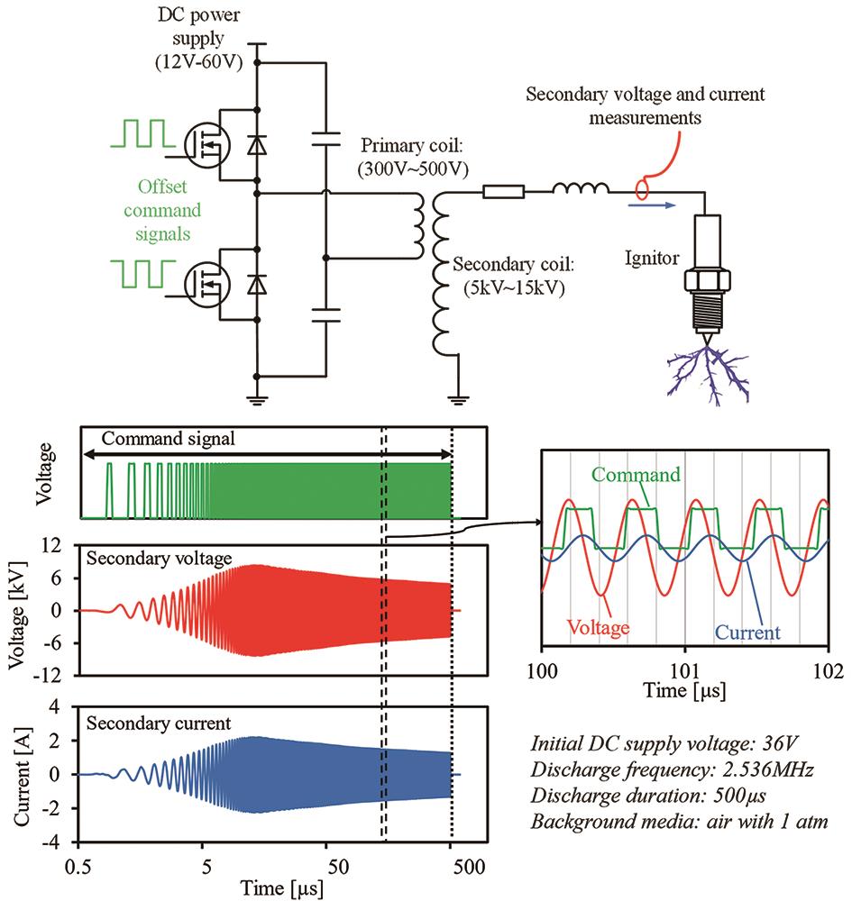
Figure 3. Experimental circuit and electrical waveforms of the oscillating plasma ignition system [16].
3. Challenges of Plasma Discharge under Engine Conditions
As shown in Figure 2, a typical plasma discharge system consists of a direct current (DC) power supply, a power drive, and a plasma antenna. A pulsed-train command with a favorable oscillating frequency is applied to stimulate the plasma power drive, aiming to generate a high voltage at the plasma antenna. Unlike conventional spark plugs utilizing a ground electrode to guide the direction of the plasma channel, the plasma ignition system releases the plasma streamers by ionizing the gaseous media around the antenna [26]. The ionized surrounding media becomes a part of the discharging circuit, and plasma discharge is thus affected by the changes in background conditions [27,28]. Figure 4 lists potential factors that may affect the plasma discharge. These factors include ignition control, background conditions, and external disturbances.
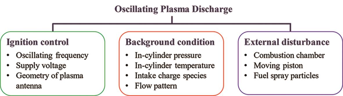
Figure 4. Impacts on oscillating plasma discharge under engine-like conditions.
3.1. Challenges of Ignition Control
The oscillating frequency of the power drive can be adjusted by a pulse train command. However, the oscillating frequency needs to match the optimal working frequency of a system (resistor-inductor-capacitor (RLC) electrical resonance frequency) for plasma discharge. The optimal working frequency is determined by the hardware setup [29]. Figure 5 shows waveforms of discharge voltage and current with the impact of oscillating frequency on energy and discharge voltage.
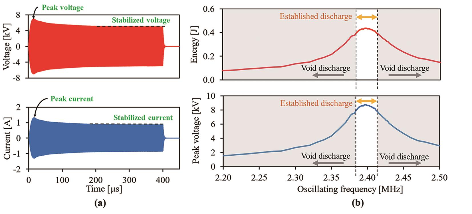
Figure 5. Voltage and current measurements in the time domain (a), discharge energy, and peak voltage in the frequency domain (b) (adapted with permission from Yu et al. [19]).
Under the time domain, during the plasma oscillation, the amplitudes of discharge voltage and current waveforms increase initially until reaching the peak values. In order to sustain the plasma discharge, the amplitudes decrease and stabilize subsequently. As shown in Figure 5b, the oscillating frequency needs to be modulated within a narrow bandwidth (~0.03 MHz) to generate sufficient discharge voltage to establish a plasma discharge. Discharging bandwidth is affected by background conditions and disturbances. Under engine conditions, elevated cylinder pressure can suppress the plasma discharge event, and the discharging bandwidth is narrowed consequently [24]. Thus, the strict requirements of oscillating frequency modulation demand control systems with high accuracy and fast response.
The peak discharge voltage is determined by the DC power supply voltage, which needs to be controlled within a strict range to establish plasma discharge. For instance, under the experimental setup in this work, the DC power supply voltage lower than 30 V is not sufficient to generate plasma discharge; however, a supply voltage higher than 80V will trigger an unwanted arc discharge.
Since plasma discharge relies on the initial ionization of the gas media in the vicinity of the plasma antenna, the electric field gradient is thus an important parameter affecting the plasma discharge event [24,28]. Under similar discharge voltage, the electric field gradient is influenced by the geometry of the antenna tip. Empirical results indicate that the plasma is easy to discharge from the antenna with a sharper tip. The wear and erosion of the antenna will degrade the electric field gradient, leading to void discharge even under the same discharge voltage.
3.2. Impacts of Background Conditions
The direct images in Figure 6 show the oscillating plasma discharge in Nitrogen under various background pressures [16]. Theoretically, the oscillating plasma discharge under vacuum conditions tends to generate relatively homogeneous plasma. It can be observed that a diffusive plasma discharge exists under 0.1 bar absolute pressure, but transits to streamer discharge under 1 bar. Under higher background pressure, the mean free path of the particles is decreased, and the collision frequency increases. The plasma streamer length is shortened from approximately 22 mm to 2 mm, as the background pressure further increases from 1 bar to 5 bar. Thus, the advantage of oscillating plasma discharge over spark discharge is compromised under higher background pressure.
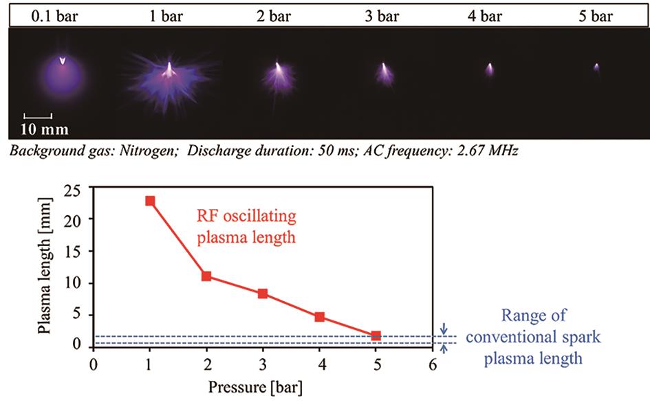
Figure 6. Oscillating plasma discharge under elevated pressure conditions [16].
Figure 7 demonstrates the background pressure impact on the oscillating plasma discharge and flame kernel formation. Overall, compared with the conventional spark ignition shown in Figure 1, the plasma discharge can generate a bigger initial flame kernel with more wrinkles at the flame front. It is noticed that under elevated background pressure, both the size and number of the streamers decrease, resulting in a smaller initial flame kernel. The elevated pressure results in the volume shrinkage of the initial flame kernel area. However, small but dense flame kernels are formed along the streamers, which further contribute to the dense flame front wrinkles and more intensified successful ignition sites.
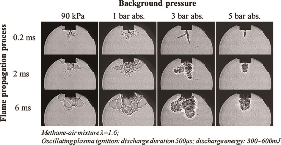
Figure 7. Shadowgraph imaging of flame kernel development initiated by oscillating plasma under a pressurized mixture.
The background gas composition and pressure often lead to different ionization coefficients, attachment coefficients, and the mobility status of the space charges [30,31]. Thus, it is important to investigate the influence of background gas ionization and pressure on the plasma discharge. A higher background temperature enhances the kinetic energy of the air molecules, which benefits the plasma discharge. The minimum voltage required for plasma discharge decreases with the increase in the background temperature [32].
The impact of the flow pattern on plasma discharge is less understood, but preliminary research in the authors’ work suggests a marginal impact of flow speed on plasma discharge. Considering the plasma discharge with an oscillating frequency of approximately 2 MHz, the building-up process is normally within microseconds. With cross flow speed of 30 m/s, which is considered a high in-cylinder flow motion, the moving distance within each oscillation cycle is around tens of micrometers. Because the size of normal plasma discharge is around 5–10 mm even under elevated background pressure conditions, the air movement is negligible.
3.3. Impacts of Other External Disturbances
Because of the absence of the ground electrode, the distribution of the electric field close to the antenna tip can be easily distorted by external disturbances. A touchdown of the plasma streamers to the ground is recognized as an arc discharge. The approach of a piston during spark event near engine compression TDC, or combustion chamber geometry can significantly increase the arcing tendency. Once the unwanted arc discharge takes place, the electric field around it changes rapidly and collapses, and a strong current surge can be noticed on the discharge waveform. The current surge during the arc discharge can generate heat, hence accelerating the wear of the antenna tip [23]. The discharge voltage waveforms of three typical oscillating plasma discharge events are plotted in Figure 8 including the void discharge, established discharge, and arc discharge.
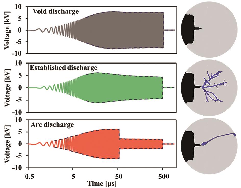
Figure 8. The comparison of the measured discharge voltage of void, established, and arc discharge events (adapted with permission from Wang et al. [22]).
The black dash lines shown in Figure 8 indicate the amplitude of the voltage waveforms. When the command pulse train is sent to the plasma power drive, the oscillation begins in the plasma ignition system. The discharge voltage keeps increasing until it reaches the peak value. When the plasma fails to release from the antenna, the voltage amplitude stays relatively stable throughout the commanded duration. However, with established plasma discharge, the waveform envelopes decline slightly and stabilize until the command ends. In an arc discharge event, when the plasma streamers touch down to a metal surface, the discharge voltage drops immediately from 6 kV to 2 kV.
Carbon deposits generated by incomplete combustion and unburned fuel droplets can attach to the surface of the ceramic insulator. The degraded insulation leads to surface discharge and arc discharge, which will compromise the ignition capability of the plasma streamers.
Therefore, a stable plasma discharge under engine conditions remains to be a challenge. Control models and strategies that can predict normal and abnormal discharging events based on discharge waveforms will enable the dynamic control of the plasma system. Therefore, plasma discharge characteristics need to be further investigated via electrical waveform measurements and analysis.
4. Conclusions
This study investigates and discusses the advances and challenges of oscillating plasma discharge for clean combustion and industrial applications. The major conclusions are:
- The streamers released from the oscillating plasma antenna can stretch beyond the size of the conventional spark gap and establish a much bigger ignition volume. The enhancement of the burning rate and acceleration of the flame kernel growth is contributed by the flame front distortion contributed by the high frequency oscillating electric field.
- The oscillating frequency needs to be modulated precisely within a narrow bandwidth (~0.03 MHz) to achieve successful plasma discharge, which demands control systems with high accuracy and fast response.
- Under elevated background pressure, both the size and number of the streamers decrease, resulting in a smaller initial flame kernel. The plasma streamer length is shortened from approximately 22 mm to 2 mm, as the background pressure increases from 1 bar to 5 bar absolute pressure.
- A stable plasma discharge under engine conditions remains to be a challenge. The external disturbances, e.g., piston moving might cause unwanted arc discharge. More analysis and strategies that can predict normal and abnormal discharging events will enable the dynamic control of the oscillating plasma system.
Author Contributions: Conceptualization, M.Z., X.Y. and G.R.; Methodology, X.Y. and L.W.; Software, L.W.; Validation, L.W.; Formal analysis, L.W. and X.Y.; Investigation, L.W.; Resources, L.W.; data curation, L.W. and X.Y.; Writing—Original draft preparation, L.W. and G.R.; Writing—review and editing, L.W.; Visualization, G.R.; supervision, X.Y., M.Z., and G.R.; Project administration, M.Z.; Funding acquisition, M.Z. All authors have read and agreed to the published version of the manuscript.
Funding: This research received no external funding
Acknowledgments: The research at the Clean Combustion Engine Laboratory is partially sponsored by: Natural Sciences and Engineering Research Council of Canada (NSERC) —Industrial Research Chairs Grants (IRC), Collaborative Research and Development Grants (CRD), Research Tools and Instruments grants program (RTI), Discovery Grants (individual) program (DG); Canada Foundation for Innovation (CFI) —Ontario Research Foundation (ORF); and the University of Windsor. Special thanks to Torch and other Original equipment manufacturers (OEMs) for their technical support, and Clean Combustion Engine Lab (CCEL) colleagues’ contribution in their time.
Conflicts of Interest: The authors declare no conflict of interest.
References
- Takahashi, D.; Nakata, K.; Yoshihara, Y.; et al. Combustion Development to Achieve Engine Thermal Efficiency of 40% for Hybrid Vehicles. SAE Technical Paper 2015, No. 2015-01–1254. DOI: https://doi.org/10.4271/2015-01-1254
- Galloni, E.; Fontana, G.; and Palmaccio, R. Effects of Exhaust Gas Recycle in a Downsized Gasoline Engine. Applied Energy 2013, 105, 99–107. DOI: https://doi.org/10.1016/j.apenergy.2012.12.046
- Liu, Z. Alternative Fuels in Automotive Vehicles. International Journal of Automotive Manufacturing and Materials 2023, 2(1), 7. DOI: https://doi.org/10.53941/ijamm0201007
- Yu, X.; Sandhu, N.S.; Yang, Z. Suitability of Energy Sources for Automotive Application—A Review. Applied Energy 2020, 271, 115169. DOI: https://doi.org/10.1016/j.apenergy.2020.115169
- O'Connor, J.; Borz, M.; Ruth, D.; et al. Optimization of an Advanced Combustion Strategy Towards 55% BTE for the Volvo SuperTruck Program. SAE International Journal of Engines 2017, 10(3), 1217–1227. DOI: https://doi.org/10.4271/2017-01-0723
- Dec, J.E. Advanced compression-ignition engines—understanding the in-cylinder processes. Proceedings of the Combustion Institute 2009, 32(2), 2727–2742. DOI: https://doi.org/10.1016/j.proci.2008.08.008
- Schumann, F.; Sarikoc, F.; Buri, S.; et al. Potential of spray-guided gasoline direct injection for reduction of fuel consumption and simultaneous compliance with stricter emissions regulations. International Journal of Engine Research 2013, 14(1), 80–91. DOI: https://doi.org/10.1177/1468087412451695
- Huang, C.C.; Shy, S.S.; Liu, C.C.; et al. A transition on minimum ignition energy for lean turbulent methane combustion in flamelet and distributed regimes. Proceedings of the Combustion Institute 2007, 31(1), 1401–1409. DOI: https://doi.org/10.1016/j.proci.2006.08.024
- Ju, Y.; Sun, W. Plasma assisted combustion: Dynamics and chemistry. Progress in Energy and Combustion Science 2015, 48, 21–83. DOI: https://doi.org/10.1016/j.pecs.2014.12.002
- Starikovskaia, S.M. Plasma assisted ignition and combustion. Journal of Physics D: Applied Physics 2006, 39(16), R265. DOI: https://doi.org/10.1088/0022-3727/39/16/R01
- Wolk, B.; Ekoto, I. Calorimetry and atomic oxygen laser-induced fluorescence of pulsed nanosecond discharges at above-atmospheric pressures. In Ignition Systems for Gasoline Engines: 3rd International Conference, November 3–4, 2016, Berlin, Germany 3 (pp. 169–189). Springer International Publishing: Berlin, Germany. DOI: https://doi.org/10.1007/978-3-319-45504-4_10
- Hicks, A.; Norberg, S.; Shawcross, P.; et al. Singlet oxygen generation in a high pressure non-self-sustained electric discharge. Journal of Physics D: Applied Physics 2005, 38(20), 3812. DOI: https://doi.org/10.1088/0022-3727/38/20/007
- Bentaleb, S.; Blin-Simiand, N.; Jeanney, P.; et al. Ignition of lean air/hydrocarbon mixtures at low temperature by a single corona discharge nanosecond pulse. Aerospace Lab 2015, (10).
- Wu, L.; Lane, J.; Cernansky, N.P.; et al. Plasma-assisted ignition below self-ignition threshold in methane, ethane, propane and butane-air mixtures. Proceedings of the Combustion Institute 2011, 33(2), 3219–3224. DOI: https://doi.org/10.1016/j.proci.2010.06.003
- Takashima, K.; Zuzeek, Y.; Lempert, W.R.; et al. Characterization of a surface dielectric barrier discharge plasma sustained by repetitive nanosecond pulses. Plasma Sources Science and Technology 2011, 20(5), 055009. DOI: https://doi.org/10.1088/0963-0252/20/5/055009
- Yu, X.; Wang, L.; Yu, S.; et al. Flame kernel development with radiofrequency oscillating plasma ignition. Plasma Sources Science and Technology 2022, 31(5), 055004. DOI: https://doi.org/10.1088/1361-6595/ac5f21
- Wang, L. Characterization of Corona Discharge for Ignition Improvement. Ph.D. degree, University of Windsor, Windsor, N9B 3P4 Ontario, Canada, 2019.
- Yu, S.; Zheng, M. Future gasoline engine ignition: A review on advanced concepts. International Journal of Engine Research 2021, 22(6), 1743–1775. DOI: https://doi.org/10.1177/1468087420953085
- Yu, X.; Tan, Q.; Wang, L.; et al. Chapter 8 - Predictive Modeling of Oscillating Plasma Energy Release for Clean Combustion Engines. In: Predictive Modelling for Energy Management and Power Systems Engineering, Deo, R., Samui, P., Roy, S.S., eds.; Elsevier: Amsterdam, the Netherlands, 2021, pp. 233–247. DOI: https://doi.org/10.1016/B978-0-12-817772-3.00008-2
- Fansler, T.D.; Reuss, D.L.; Sick, V.; et al. Invited Review: Combustion instability in spray-guided stratified-charge engines: A review. International Journal of Engine Research 2015, 16(3), 260–305. DOI: https://doi.org/10.1177/1468087414565675
- Schenk, M.; Schauer, F.X.; Sauer, C.; et al. Challenges to the Ignition System of Future Gasoline Engines – An Application Oriented Systems Comparison. In: Ignition Systems for Gasoline Engines. Günther, M., Sens, M., eds.; Springer International Publishing: Cham, Switzerland, 2017, pp. 3–25. DOI: https://doi.org/10.1007/978-3-319-45504-4_1
- Wang, L.; Yu, X.; Zheng, M. Ignition Energy Discharge of Oscillating Plasma Waveforms Under Atmospheric Conditions. IEEE Transactions on Plasma Science 2020, 49(1), 326–334. DOI: https://doi.org/10.1109/TPS.2020.3041635
- Wang, L.; Tan, Q.; Yu, S.; et al. A Framework for the Active Control of Corona Ignition Systems. SAE Technical Paper 2019, No. 2019-01–2157. DOI: https://doi.org/10.4271/2019-01-2157
- Burrows, J.; Lykowski, J.; Mixell, K. Corona ignition system for highly efficient gasoline engines. MTZ Worldwide 2013, 74(6), 38–41. DOI: https://doi.org/10.1007/s38313-013-0062-z
- Bohne, S.; Rixecker, G.; Brichzin, V.; et al. High-frequency ignition system based on corona discharge. MTZ Worldwide 2014, 75(1), 30–35. DOI: https://doi.org/10.1007/s38313-014-0007-1
- Idicheria, C.A.; and Najt, P.M. Potential of Advanced Corona Ignition System (ACIS) for Future Engine Applications. In: Ignition Systems for Gasoline Engines. Günther, M., Sens, M., eds.; Springer International Publishing, Cham, Switzerland, 2017, pp. 315–331. DOI: https://doi.org/10.1007/978-3-319-45504-4_19
- Singleton, D.; Pendleton, S.J.; Gundersen, M.A. The role of non-thermal transient plasma for enhanced flame ignition in C2H4–air. Journal of Physics D: Applied Physics 2010, 44(2), 022001. DOI: https://doi.org/10.1088/0022-3727/44/2/022001
- Auzas, F.; Tardiveau, P.; Puech, V.; et al. Heating effects of a non-equilibrium RF corona discharge in atmospheric air. Journal of Physics D: Applied Physics 2010, 43(49), 495204. DOI: https://doi.org/10.1088/0022-3727/43/49/495204
- Suess, M.; Guenthner, M.; Schenk, M.; et al. Investigation of the potential of corona ignition to control gasoline homogeneous charge compression ignition combustion. Proceedings of the Institution of Mechanical Engineers, Part D: Journal of Automobile Engineering 2012, 226(2), 275–286. DOI: https://doi.org/10.1177/0954407011416905
- Braithwaite, N.S.J. Introduction to gas discharges. Plasma Sources Science and Technology 2000, 9(4), 517. DOI: https://doi.org/10.1088/0963-0252/9/4/307
- Schnyder, R.; Howling, A.A.; Bommottet, D.; et al. Direct current breakdown in gases for complex geometries from high vacuum to atmospheric pressure. Journal of Physics D: Applied Physics 2013, 46(28), 285205. DOI: https://doi.org/10.1088/0022-3727/46/28/285205
- Yan, P.; Zheng, C.; Zhu, W.; et al. An experimental study on the effects of temperature and pressure on negative corona discharge in high-temperature ESPs. Applied Energy 2016, 164, 28–35. DOI: https://doi.org/10.1016/j.apenergy.2015.11.040


