

Downloads
Download


This work is licensed under a Creative Commons Attribution 4.0 International License.
Article
Transient Nozzle-Exit Velocity Profile in Diesel Spray and Its Influencing Parameters
Ya Gao 1, Weidi Huang 2,*, Raditya Hendra Pratama 2, and Jin Wang 1
1 Advanced Photon Source, Argonne National Laboratory, 9700 S Cass Ave, Lemont, IL 60439, United States
2 Research Institute for Energy Conservation, National Institute of Advanced Industrial Science and Technology, Ibaraki 305-8564, Japan
* Correspondence: wd.huang@aist.go.jp
Received: 24 September 2022
Accepted: 10 November 2022
Published: 25 December 2022
Abstract: The primary breakup in the diesel spray relies closely on the initial dynamics at the nozzle exit. However, solid experimental results are still missing due to the great difficulties in measuring the near-nozzle spray dynamics. This study proposed an investigation focusing on the transient nozzle-exit spray dynamics by taking advantage of the X-ray phase contrast imaging technique. The in-nozzle needle motion, spray morphology, and dynamics at a commercial diesel nozzle exit were obtained. Experimental results were then examined, linking with the needle motion to understand the transient spray dynamics. The effect of the initial conditions (i.e., the injection pressure and ambient density) on the resulting trends were also considered. It is found that the nozzle-exit spray morphology and velocity profile highly relate to the in-nozzle needle lift. Once the needle sufficiently opens, the spray reaches steady status, and the nozzle-exit velocity becomes almost constant. The spray width slightly increases with the increasing ambient gas density or the decreasing injection pressure. Injection pressure significantly affects the spray velocity amplitude, whereas the ambient gas density alters the spray-velocity profiles mainly in the periphery of the spray. Finally, an analytic analysis was conducted to further examine the transient spray axial velocity with the changing radial locations. It is found the nozzle-exit spray velocity can be predicted in the Gaussian-type formula. This feature likely relates to in-nozzle flow characteristics.
Keywords:
transient spray velocity diesel spray needle motion near-nozzle spray x-ray imaging1. Introduction
The structure of direct injection sprays close to the nozzle plays an important role in the pre-ignition mixing process. Investigation of the near-nozzle spray structure is necessary to understand the relationship between the initial conditions, the nozzle geometries, and the resulting mixture characteristics. Particularly in the diesel engine, the injected spray reacts with the compressed air and directly combusts during the injection. The precise control of injection events can significantly optimize diesel engine performances and reduce pollutant emissions.
The fuel spray characteristics are typically investigated using visible-light diagnostic techniques, such as spray characteristics under different initial conditions (i.e., injection pressures [1,2] and ambient conditions [3,4]), different nozzle geometries [5,6], and different fuel properties [7,8]. These investigations proved that the extremely high-speed relative motion between the liquid jets and environment gas is one of the key factors causing jet breakup and atomization. However, because of the highly transient and multiphase process of fuel injection, the inherent mechanism of jet breakup and evaporation has not been conclusively determined yet.
It is well known that two breakup processes are involved in the diesel spray: primary breakup and secondary breakup. The secondary breakup has been well discussed through the aforementioned investigations, whereas the primary breakup is still limited understood. The primary breakup in the diesel spray occurs majorly in the near-nozzle region, i.e., dense spray field. It is difficult to visualize the dense spray field using conventional visible-light diagnostic techniques, even though some methods have been proposed [9–11]. Instead, simulation investigations can be extensively found regarding the primary breakup in the near-nozzle field [12–15]. The simulation results indicated that the primary breakup in the diesel spray primarily relies on the initial dynamics at the nozzle exit, which is further linked with the in-nozzle flow characteristics. However, the primary breakup process is not well understood due to the lack of solid experimental results.
In the last decade, X-ray diagnostics have been increasingly used in the experimental investigations of near-nozzle spray dynamics. X-rays have high penetrating power and short wavelength compared to visible lights, which minimizes the beam scattering from gas-liquid interfaces [16,17]. In addition, the high-flux x-rays available at synchrotron sources permit sufficiently high spatial and temporal resolution to capture the transient dynamics in fuel sprays. On the one hand, X-ray radiography techniques provide quantitative line-of-sight measurements of fluid density. A three-dimensional representation of the density distribution may be estimated by solving an analytical function for the mean density using projection data from a small number of viewing angles [18–20]. On the other hand, X-ray phase-contrast imaging (XPCI) technique is particularly successful in imaging the interior of a metal nozzle and near-nozzle primary spray breakup with a nanosecond-level temporal resolution. Studies have been performed using this technique to analyze the needle motion inside practical nozzles [21–23], in-nozzle flows [24–26], and near-nozzle spray dynamics [27–29].
The injection pulse is increasingly shortened in modern diesel engines to achieve ultra-optimized combustion control. In such scenarios, the needle lifts are typically low, where the spray dynamics could be highly transient. In this study, by taking advantage of the XPCI technique, we proposed an investigation focusing on the transient nozzle-exit spray dynamics. Firstly, the needle motion of a commercial diesel nozzle was measured using the XPCI technique. Then, the spray morphology and its dynamics at the nozzle exit were examined, linking with the needle motion. Initial conditions, i.e., the injection pressure and ambient density, were also included in the study. Finally, the discussion was made to understand the transient nozzle-exit spray dynamics and their relationship with the influencing parameters. By conducting this study, it is expected to contribute to an improved comprehensive understanding of the transient spray dynamics at the nozzle exit. Nevertheless, the current investigation could result in following investigations both in experiment or simulation to discuss the effect of the transient spray dynamics at the nozzle exit on the downstream mixture formation and combustion.
2. Methods
2.1. ExperImental Setup
The experiments in this study were performed at the 7IDB station of the Advanced Photron Source (APS) using the XPCI technique. First, a brief introduction is made to the XPCI technique. X-ray has a considerably short wavelength, high energy, and high brilliance in contrast to visible light. These features of X-ray particularly favor direct imaging of the liquid droplets without severe scattering and absorption, where the primary breakup in fuel sprays occurs. The X-ray’s energy absorption and phase shift arise simultaneously when an X-ray beam propagates through an object. As regards a soft-material object, like the fuel spray, the phase shift of X-ray after an X-ray beam propagates through the object is generally three orders of magnitude larger than its energy attenuation [30]. This feature has made the XPCI technique particularly suitable to visualize the near-nozzle primary breakup in fuel sprays under an ultra-high temporal resolution (nanosecond-level). Details on the XPCI techniques can also be referred to in our previous publications [31,32].
Figure 1 illustrates the experimental setup for the XPCI technique. Electrons circle at the speed of light in a storage ring. Insertion devices, i.e., different types of magnets, are used in the storage ring to alter the electron-traveling path, and X-ray beams are produced in this process. A mechanical chopper then chopped the emitted X-ray beam to transmit the X-ray only at the imaging instant such that the experimental system can be protected from the X-ray heat load. When the X-ray beam passed through the spray, a phase-contrast image of the spray was formed, which was converted using a scintillator crystal (LuAg:Ce) to visible lights. The converted visible-light image was then reflected on a 45-degree mirror and recorded by a high-speed camera (Model SA-Z, Photron Inc.). The high-speed camera was synchronized with the synchrotron revolution frequency of 271 kHz. The higher the image rate, the smaller the image view field becomes. As a result, the high-speed camera was triggered once every four revolutions of the synchrotron and stored at 68 kHz. A delay generator was used to synchronize the fuel injection and the timing of the incoming X-ray beam, as well as the high-speed camera start-recording trigger. The view field of the images was 1.1 mm × 1.1 mm, and the spatial resolution of the images was 2.5 μm/pixel.
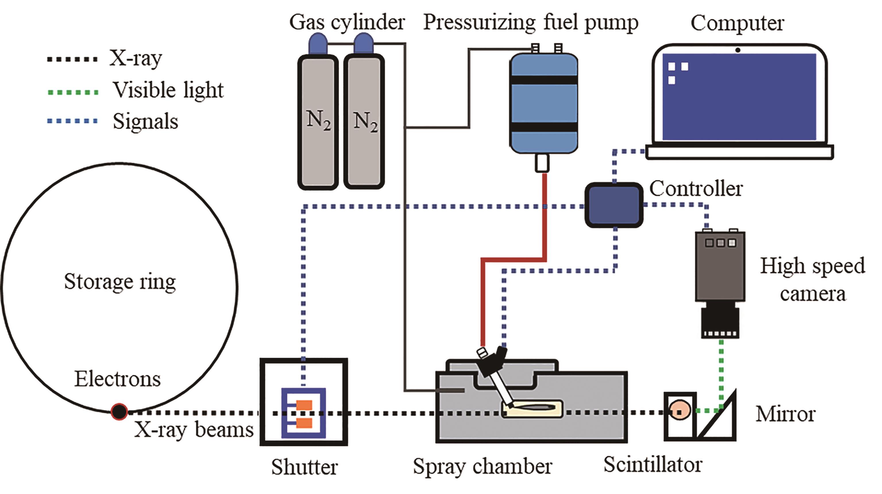
Figure 1. Experimental setup for the X-ray phase-contrast imaging.
2.2. ExperImental Conditions
The experimental conditions are presented in Table 1. The injector used in this investigation was a 7-hole piezo injector with 0.12 mm in hole diameter. This study was to examine the transient nozzle-exit spray dynamics. The in-nozzle needle motion and only one spray from the seven spray plumes were measured. The ambient gas temperature in the spray chamber was fixed to room temperature. The applied injection-pulse duration was 0.5 ms for all the conditions. Two practical injection pressures of 100 MPa and 200 MPa were applied. Four ambient gas densities were considered at each injection pressure, including 1.25, 7.50, 15.7, and 23.2 kg/m3. Detailed information on the experimental conditions can be referred to in Table 1.
Table 1. Experimental conditions.

2.3. Data Analysis
Figure 2 shows the pulse timing pattern of the Hybrid-Fill mode generated in the APS. The Hybrid-Fill beam mode has an irregular pulse pattern with a cycle period of 3.682 μs. This pulse pattern contains a single-bunch with a 150 ps duration and a 16 mA current isolated from the remaining eight groups of 7 consecutive bunches (8 septets) by symmetrical 1.594 μs. The group bunches have 11 mA current per group, a periodicity of 68 ns, and a gap of 51 ns between groups, with the total length of the bunch train being 500 ns.
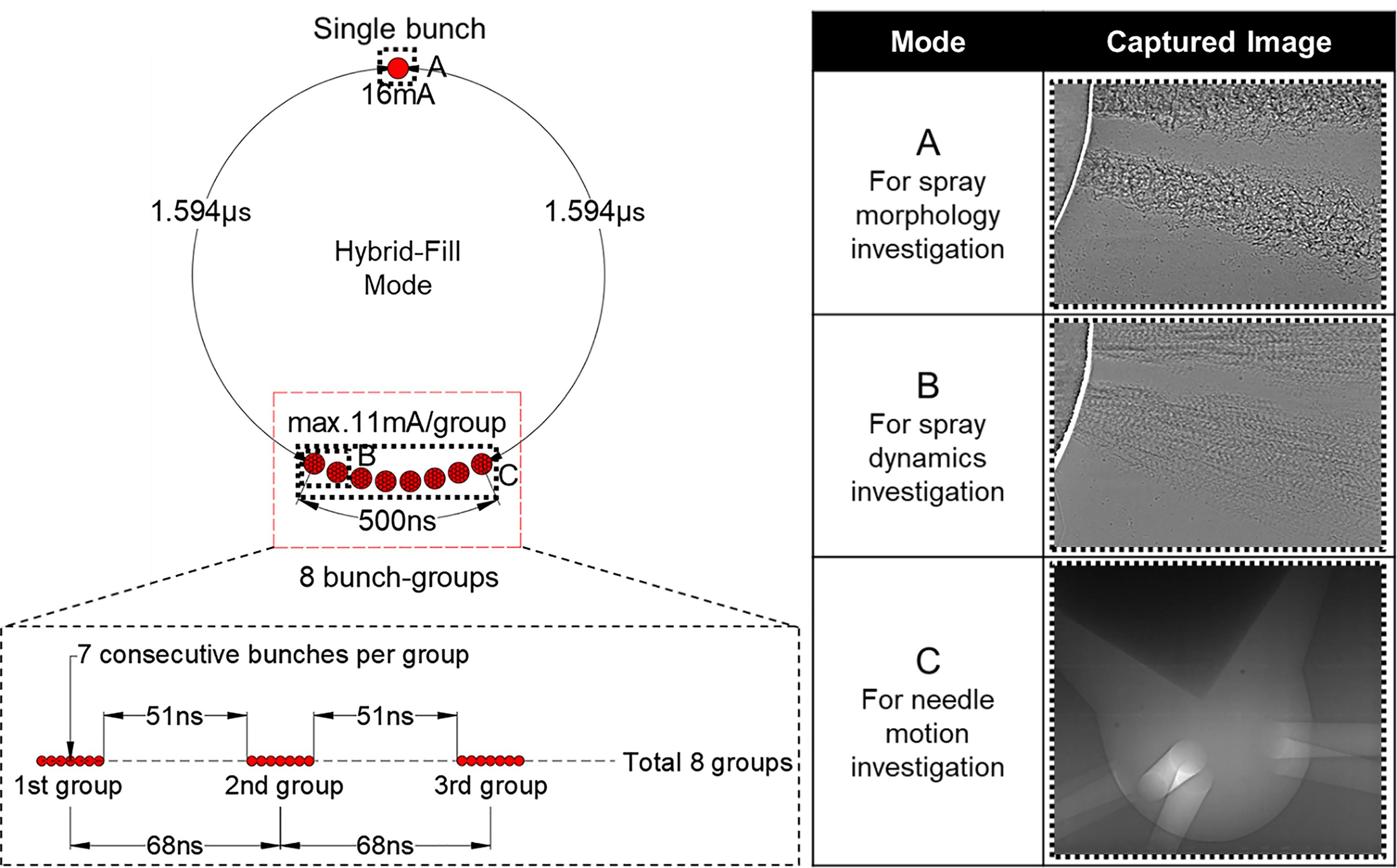
Figure 2. X-ray pulse timing patterns and modes used for single-exposure spray imaging, double-exposure spray imaging, and needle motion imaging.
The single bunch, i.e., mode A in this experiment, was used to get a still image of the spray. In this experiment, a double-exposed image of the spray was obtained using two consecutive bunch groups, called mode B. Based on analyzing the double-exposed spray pattern on the image, the local velocity of the spray can be known. Details will be explained in the later section. In this experiment, eight consecutive bunch groups, i.e., mode C, were used to get a bright image of needle motion inside the injector. The needle motion speed is relatively slow compared to the total exposure time, and the obtained image is sharp without any multi-exposure pattern and motion blur.
Figure 3 illustrates the auto-correlation method for spray velocity and needle lift measurements. The time-sequential images of the needle motion can be obtained through high-speed X-ray imaging. First, a region of interest covering the needle tip (base window) was set in a frame before the needle opens, representing the initial needle location. Second, a searching window having the same size as the base window was set in the frame to calculate (regarded as the calculation frame). Next, the similarity factor R between these two windows could be obtained using the two-dimensional cross-correlation calculation. By incrementally shifting the search window’s location in the calculation frame and repeating the calculation, a series of R can be extracted corresponding to each search window’s location. Their maximum indicates where the search window’s cropped image perfectly matches the base window. Once the maximum cross-correlation is detected, needle lift can be known by counting the search window’s displacement relative to the base window. An explanation of needle-motion calculation can also refer to our previous study [33].

Figure 3. Autocorrelation method for needle lift and spray velocity measurement.
A double-exposed X-ray image that shows a double-exposed pattern along the spray enables us to do an auto-correlation analysis. A window to analyze the local velocity of the spray was determined by considering the spray pattern size so that the displacement of the spray pattern could be obtained. Knowing the time interval between the X-ray electron bunch, i.e., 68 ns, the velocity can be calculated by dividing the displacement by the time interval. Since a similar pattern with the determined window can be found at some distance within the interrogation area, a post-filtering analysis was conducted to filter the error output data, which leads to a high-accuracy spray dynamics measurement. More details on the spray velocity calculation using the XPCI technique can be referred to in our previous study [34].
3. Experimental Results
3.1. Nozzle-Exit Spray Dynamics at Varied Needle Lifts
Figure 4 shows the image sequence of the injected spray within 3 mm from the nozzle exit. The images were obtained under an injection pressure of 200 MPa and an ambient gas density of 1.25 kg/m3 and then were sorted according to the corresponding needle motion. As shown in Figure 4, the spray appears from the nozzle exit at a needle lift of 0.03 mm, or 0.1 ms, approximately after the needle lifts. This critical value is constant during the repeating measurement (ten shots per condition). The delay between the spray appearing and the needle rising should likely represent the time needed for the fuel to pass through the nozzle sac and nozzle hole. When the needle is initially opened, the spray disperses rapidly, and the gap between the two spray plumes almost disappears. Then, the spray gets shrinker and steadier with increasing needle lift. As the needle declines again, the spray gradually becomes unsteady. A sharp spray dispersion can be seen at the low needle lift.

Figure 4. Sequence of high-speed images of the injected spray (Pinj = 200 MPa, ρ = 1.25 kg/m3, and Time ASOI stands for the time after the start of injection triggering signal).
The spray dynamics at various needle motions are presented in Figure 5. The spray velocity was primarily used to represent the spray dynamics, measured at a location of 1 mm from the nozzle exit. It has been mentioned earlier that multiple simulation results indicate that the primary breakup in the diesel spray closely links with the initial dynamics at the nozzle exit, which is further linked with the in-nozzle flow characteristics. As a result, the spray dynamics at the nozzle exit are of particular interest for investigation. It is apparent in the figure that spray velocity rises quickly with the increasing needle lift. At a needle lift of approximately 0.1 mm, the spray velocity turns almost constant, even though a slight rise can still be observed. This period can be understood as the steady state of the spray dynamics, in which the in-nozzle sac pressure has been balanced. Figure 5b. shows the spray velocity distribution with increasing radial distances. The results were obtained at a fixed needle motion and averaged from ten times repeating measurements. The lower needle lifts the wider spray becomes. The variance in the spray velocity between the spray center part and the periphery is relatively small. This variance in the spray velocity gets smaller with the increasing needle lift, indicating an intact core of the spray at the region of interest.
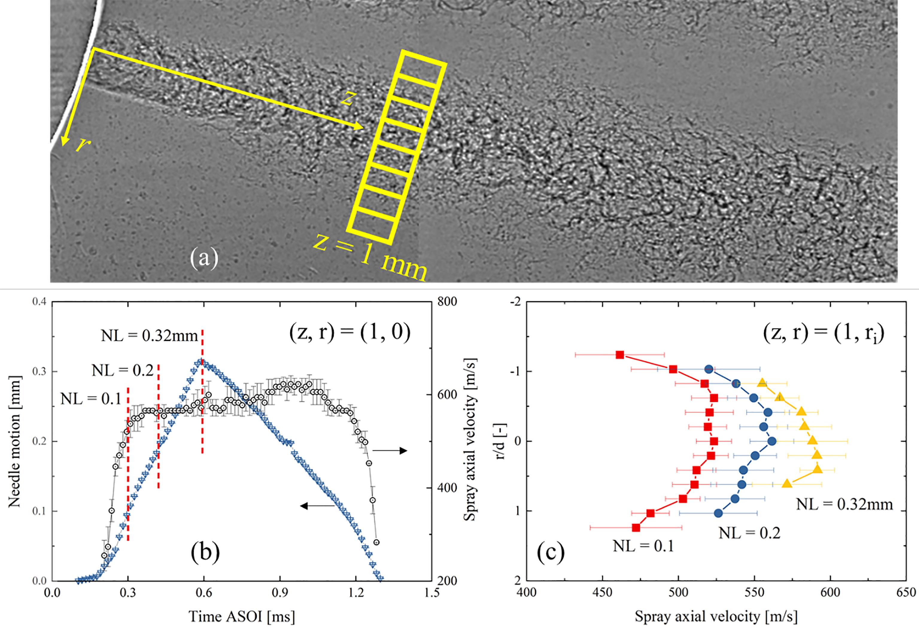
Figure 5. Spray dynamics under varied needle motion (Pinj = 200 MPa, ρ = 1.25 kg/m3): (a) spray velocity measurement; (b) needle motion and spray velocity vs. time; (c) spray velocity vs. radial locations.
3.2. Nozzle-Exit Spray Dynamics Under Varied Initial Conditions
This section will discuss the initial-condition effect on the nozzle exit spray dynamics. Figure 6 shows the high-speed images of the injected spray at various initial conditions. All the images were selected at the maximum needle lifts, which the needle lifts of 0.32 mm and 0. 22 mm for the injection pressures of 200 MPa and 100 MPa, respectively. As the injection pressure increases, the spray width slightly increases, indicating an enhanced spray dispersion at the low injection pressure. On the other hand, when the ambient gas density rises, the spray width shrinks. This seems contrary to the common knowledge that the higher the ambient gas density, the larger the spray angle arises. To explain this phenomenon, it should be noted the current XPCI technique record the spray morphology within 3 mm from the nozzle exit. In the near-nozzle region, the spray dynamics are believed to primarily depend on the in-nozzle flow characteristics rather than the aerodynamics. It is known that higher ambient gas density, i.e., ambient gas pressure, can suppress the in-nozzle flow turbulence and cavitation [35,36]. As a result, it is understood that a shrinker and steadier spray can appear at a higher ambient gas density.
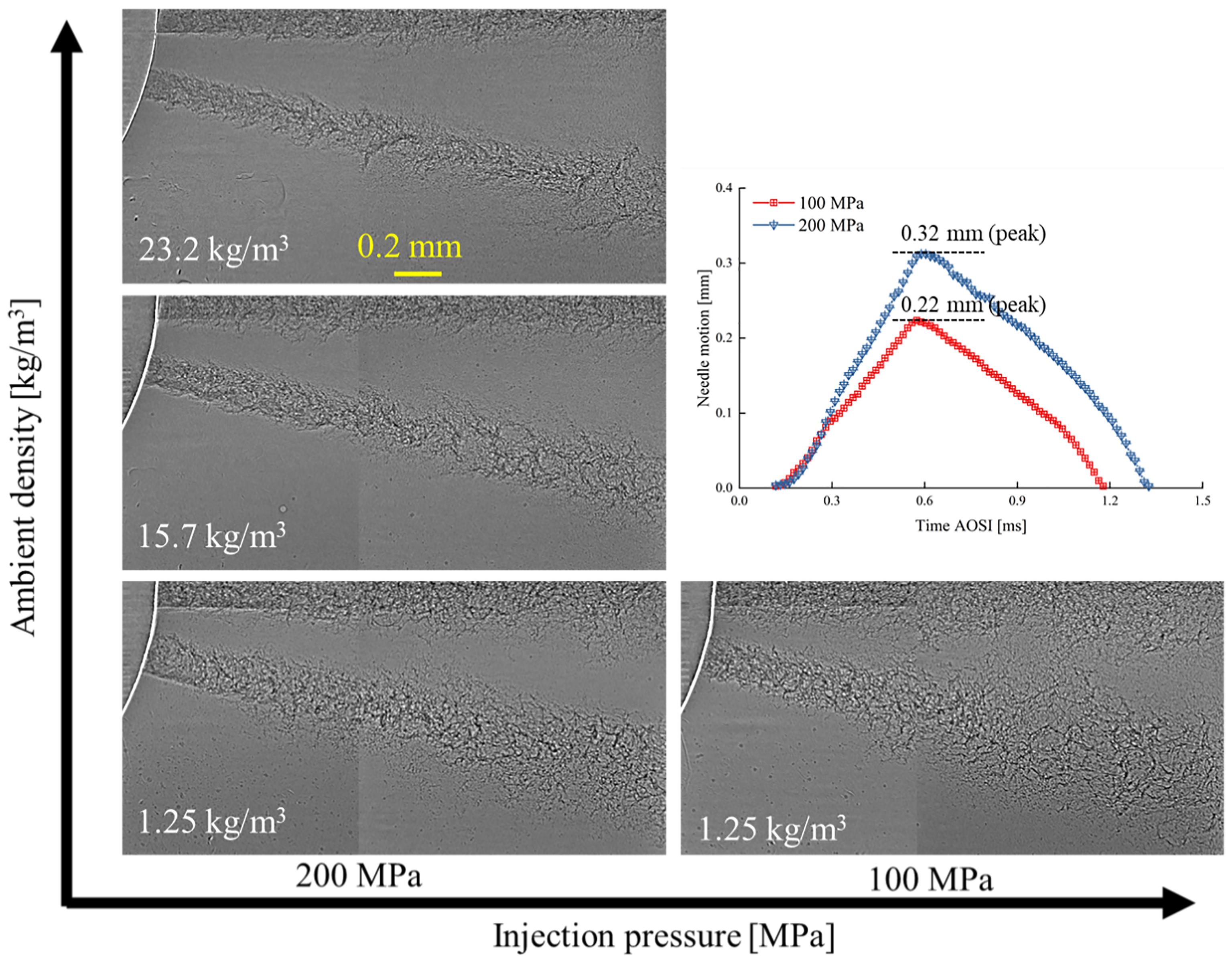
Figure 6. High-speed images of the injected spray at various initial conditions.
Figure 7 shows the spray velocities under varied ambient gas densities. The results were obtained at a fixed injection pressure of 200 MPa. The spray velocities at the center part of the spray are presented in Figure 7a. It is seen that the nozzle exit spray velocity is barely altered with the increasing ambient gas density. As explained earlier, the nozzle-exit spray dynamics rely mostly on the in-nozzle flow characteristics. The higher ambient gas densities, i.e., ambient gas pressure, can suppress the in-nozzle turbulence, benefiting an improved flow discharge coefficient. In addition, according to the Bernoulli principle, the nozzle-exit velocity depends on the pressure differential between the common rail and the ambient gas, irrelevant to the ambient gas density. As a result, the results of the spray velocities rarely changing with ambient gas densities can be understood. Figure 7b shows the spray velocity distribution with increasing radial distances. The averaged results at the steady state of the spray were used, having a needle lift over 0.2 mm. It is found that the spray velocity at the periphery declines sharply at the high ambient gas density, but this effect seems to be saturated after a particular value of the ambient gas density. This phenomenon possibly indicates a non-linear trend of the in-nozzle flow characteristics as the ambient gas density rises. More investigation on this topic is necessary for our future work.
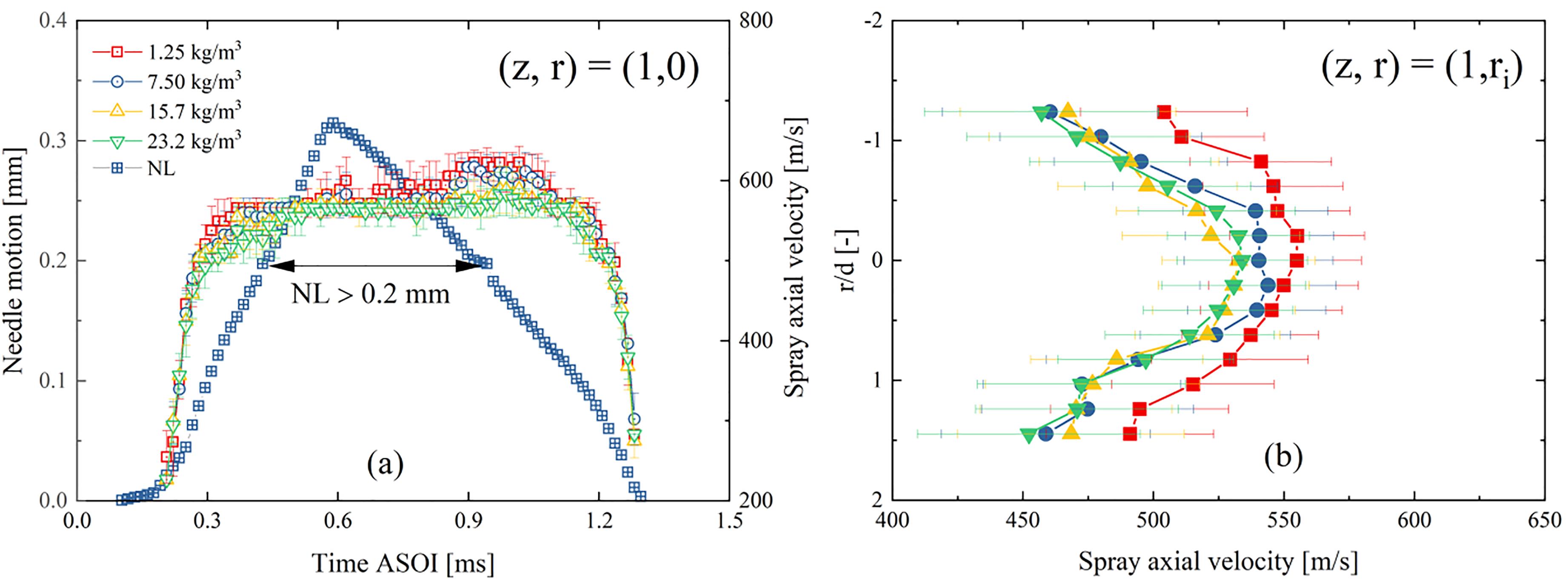
Figure 7. Spray velocities under the fixed injection pressure of 200 MPa and varied ambient gas densities: (a) needle motion and spray velocity vs. time; (b) spray velocity vs. radial locations.
4. Discussions
The spray dynamics at the nozzle exit were further examined by employing an analytic method. Multiple references have reported that the velocity field of fuel spray can be represented in the Gaussian-type formula [37–40]. However, the parameters of the formula proposed by varied researchers were slightly different. For instance, the formula proposed by Zama et al. [38] used a characteristics index of radial dispersion of spray velocity. In contrast, the formula from Payri et al. [37] predicted the spray velocity field with a characteristics index of the radial/axial location ratio. It is noted that almost all the formulas proposed until now were referred to the developed region in the spray. This is understood because the near-nozzle spray velocity is rarely reported yet due to the great difficulties in the experimental measurement. In this study, by taking advantage of the XPCI technique, the nozzle-exit spray velocity was measured at various initial conditions, as seen in Figure 8. Injection pressure significantly affects the spray velocity. Rising the ambient gas density, the spray velocity declines faster along the radial direction. Figure 8b shows the spray axial velocity, normalized by its central velocity, with the changing radial locations. It is of high interest that all the data points of the spray velocity have become greatly convergent regardless of the initial conditions. Furthermore, the normalized spray velocity and radial locations were examined using a Gaussian-type of formula, as shown in Equation (1).
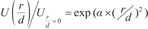
(1)
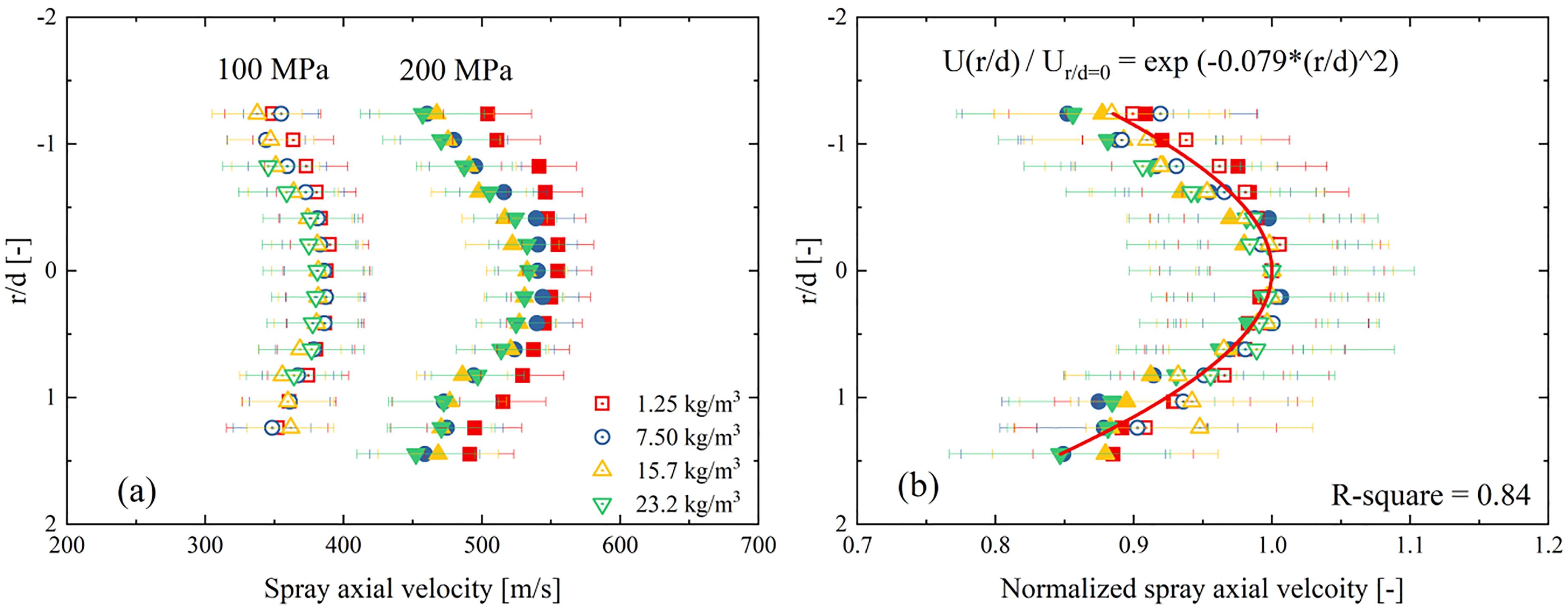
Figure 8. Spray velocity at varied radial locations: (a) the results of spray velocities; (b) the results of the normalized spray velocities.
where Ur/d=0 is the central spray velocity, and d is the nozzle hole diameter. α is the model parameter, which equals-0.079 such that the best fitting with the experimental results can be achieved. Further investigation is necessary to interpret the underlying mechanism of why the nozzle-exit velocity follows this type of profile. It is surmised that the velocity profile should link with the flow in the nozzle hole. It is well known that a fully developed flow in a pipe, i.e., the nozzle hole, has a parabolic velocity profile equivalent to Equation (1). The parabolic velocity profile in the pipe is determined by shear force due to the fuel viscosity. The nozzle used in the study has a relatively long nozzle hole (0.8 mm) and a large k-factor of 2. Thus, the in-nozzle flow exits the nozzle hole could have been stabilized. On the other hand, the nozzle-exit velocity relies on the in-nozzle flow characteristics. As a result, the nozzle-exit spray velocity profile following a resembling formula with the in-nozzle flow can be understood.
Figure 9 shows a comparison of the spray velocity between the experimental measurement and prediction using Equation (1). It is apparent that the prediction results match well with the experimental results, indicating the potential of Equation (1) in predicting the spray velocity profile even at the transient period of the spray injection. It should be mentioned that this feature likely relies on the nozzle used in the current study, which has a long nozzle hole and a large k-factor ratio. It is highly interesting to discuss the nozzle geometry effect on the nozzle-exit spray profile in our future works.

Figure 9. The prediction of the spray velocity e under varied needle lift (Pinj = 200 MPa, ρ = 1.25 kg/m3).
5. Conclusions
The primary breakup in the diesel spray relies closely on the initial dynamics at the nozzle exit. However, the solid experimental results are still missing due to the great difficulties in measuring the near-nozzle region. In this study, by taking advantage of the XPCI technique, we proposed an investigation focusing on the transient nozzle-exit spray dynamics. First, the in-nozzle needle motion, spray morphology, and dynamics at the nozzle exit of a commercial diesel nozzle were measured using the XPCI technique. Then, experimental results were examined, linking with the needle motion. Initial conditions, i.e., the injection pressure and ambient density were also included. Finally, the discussion was made to understand the transient nozzle-exit spray dynamics. The key findings of this study can be summarized below.
(1) The nozzle-exit spray morphology and velocity profile highly relate to the in-nozzle needle lift. Once the needle sufficiently opens, the spray reaches stabilized status, and the nozzle-exit velocity becomes almost constant. The variance in the spray velocity between the spray center part and the periphery is relatively small. This variance in the spray velocity gets smaller with the increasing needle lift.
(2) The spray width slightly increases with the increasing ambient gas density or the decreasing injection pressure. It is considered that the higher ambient gas density, i.e., ambient gas pressure, can suppress the in-nozzle flow turbulence and cavitation, resulting in a shrinker and steadier spray with the increasing ambient gas density. Injection pressure significantly affects the spray velocity amplitude, whereas the ambient gas density alters the spray-velocity profiles mainly in the periphery of the spray.
(3) The transient spray axial velocity, normalized by its central velocity, changes with radial locations following the Gaussian type of formula. The nozzle used in the study has a relatively long nozzle hole and a large k-factor, and the in-nozzle flow exits the nozzle hole could have been stabilized. Thus, the nozzle-exit spray can follow a resembling velocity profile with the in-nozzle flow.
Author Contributions: Conceptualization, W.H. and R.H.P.; methodology, Y.G., W.H., R.H.P. and J.W.; software, Y.G.; validation, Y.G. and W.H.; formal analysis, Y.G. and R.H.P.; investigation, Y.G., W.H., and R.H.P.; resources, Y.G. and J. W.; data curation, Y.G. and R.H.P.; writing—original draft preparation, Y.G.; writing—review and editing, W.H. and J.W.; visualization, Y.G. and R.H.P.; supervision, W.H.; project administration, W.H.; funding acquisition, W.H. All authors have read and agreed to the published version of the manuscript.
Funding: This research received no external funding.
Data Availability Statement: Not applicable.
Acknowledgments: This research and the support to Ya Gao and Jin Wang used resources of the Advanced Photon Source, a U. S. Department of Energy (DOE) Office of Science User Facility operated for the DOE Office of Science by Argonne National Laboratory under Contract No. DE-AC02-06CH11357. We acknowledge Donald Walko and Raymond Ziegler for their technical support at the 7-ID beamline of the APS.
Conflicts of Interest: The authors declare no conflict of interest.
References
- GhasemiA.; BarronR.M.; BalachandarR. Spray-induced air motion in single and twin ultra-high injection diesel sprays. Fuel 2014, 121, 284–297. https://doi.org/10.1016/j.fuel.2013.12.041.
- JiaT.-M.; Yu Y.-S.; Li G.-X. Experimental investigation of effects of super high injection pressure on diesel spray and induced shock waves characteristics. Exp. Therm. Fluid Sci. 2017; 85, 399–408. https://doi.org/10.1016/j.expthermflusci.2017.03.026.
- DesantesJ.M.; PayriR.; GarciaJ.M.; et al. A contribution to the understanding of isothermal diesel spray dynamics. Fuel 2007; 86, 1093–1101. https://doi.org/10.1016/j.fuel.2006.10.011.
- HuangW.; WuZ.; LiL.; et al. Deng J. Effect of ambient density and temperature on diesel spray characteristics. SAE Tech. Pap. 2014; 1, 1414. https://doi.org/10.4271/2014-01-1414.
- BodeM.; DiewaldF.; BrollD.O.; et al. Influence of the injector geometry on primary breakup in diesel injector systems. SAE Tech. Pap. 2014; 1, 1427. https://doi.org/10.4271/2014-01-1427.
- SalvadorF.J.; CarreresM.; JaramilloD.; et al. Analysis of the combined effect of hydrogrinding process and inclination angle on hydraulic performance of diesel injection nozzles. Energy Convers. Manag. 2015, 105, 1352–1365. https://doi.org/10.1016/j.enconman.2015.08.035.
- WangX.; HuangZ.; KutiO.A.; et al. Experimental and analytical study on biodiesel and diesel spray characteristics under ultra-high injection pressure. Int. J. Heat Fluid Flow 2010, 31, 659–666. https://doi.org/10.1016/j.ijheatfluidflow.2010.03.006.
- MoonS.; TsujimuraT.; GaoY.; et al. Biodiesel effects on transient needle motion and near-exit flow characteristics of a high-pressure diesel injector. Int. J. Engine Res. 2014, 15, 504–518. https://doi.org/10.1177/1468087413497951.
- El-HannounyE.M.; GuptaS.; PowellC.F.; et al. Near-nozzle spray characteristics of heavy-duty diesel injectors. SAE Tech. Pap. 2003, 1, 3150. https://doi.org/10.4271/2003-01-3150.
- LinneM.A.; PaciaroniM.; BerrocalE.; et al. Ballistic imaging of liquid breakup processes in dense sprays. Proc. Combust. Inst. 2009, 32, 2147–2161. https://doi.org/10.1016/j.proci.2008.07.040.
- WangZ.; DingH.; MaX.; et al. Ultra-high speed imaging study of the diesel spray close to the injector tip at the initial opening stage with single injection. Appl. Energy 2016, 165, 335–344.
- WangY.; LeeW.G.; ReitzR.; et al. Numerical simulation of diesel sprays using an Eulerian-Lagrangian spray and atomization (ELSA) model coupled with nozzle flow. SAE Tech. Pap. 2011, 1, 0386. https://doi.org/10.4271/2011-01-0386.
- HuangW.; GaoY.; LiZ.; et al. Three-dimensional investigations of flow characteristics in a diesel nozzle. Atomization Sprays 2013, 23, 343–361. https://doi.org/10.1615/AtomizSpr.2013006939.
- DongP.; InabaT.; NishidaK.; et al. Characteristics of Nozzle Internal Flow and Near-Field Spray of Multi-Hole Injectors for Diesel Engines. SAE Tech. Pap. 2015, 1, 1920. https://doi.org/10.4271/2015-01-1920.
- GhijiM.; GoldsworthyL.; BrandnerP.A.; et al. Analysis of diesel spray dynamics using a compressible Eulerian/VOF/LES model and microscopic shadowgraphy. Fuel 2017, 188, 352–366. https://doi.org/10.1016/j.fuel.2016.10.041.
- PowellC.F.; CiattiS.A.; CheongS.K.; et al. X-ray absorption measurements of diesel sprays and the effects of nozzle geometry. SAE Tech. Pap. 2004, 1, 2011. https://doi.org/10.4271/2004-01-2011.
- DukeD.J.; SwantekA.B.; SovisN.M.; et al. Time-resolved X-ray Tomography of Gasoline Direct Injection Sprays. SAE Int. J. Engines 2016, 9, 143–153. https://doi.org/10.4271/2015-01-1873.
- KastengrenA.; PowellC.F.; LiuZ.; et al. Time resolved, three dimensional mass distribution of diesel sprays measured with X-ray radiography. SAE Tech. Pap. 2009, 1, 0840. https://doi.org/10.4271/2009-01-0840.
- DukeD.J.; KastengrenA.L.; MatusikK.E.; et al. Internal and near nozzle measurements of Engine Combustion Network “Spray G” gasoline direct injectors. Exp. Therm. Fluid Sci. 2017, 88, 608–621. https://doi.org/10.1016/j.expthermflusci.2017.07.015.
- HallsB.R.; RadkeC.D.; ReuterB.J.; et al. High-speed, two-dimensional synchrotron white-beam x-ray radiography of spray breakup and atomization. Opt. Express. 2017, 25, 1605–1617.
- PowellC.F.; KastengrenA.L.; LiuZ.; et al. The effects of diesel injector needle motion on spray structure. J. Eng. Gas Turbines Power 2011, 133, 207–217. https://doi.org/10.1115/ICEF2009-14076.
- HuangW.; MoonS.; OhsawaK. Near-nozzle dynamics of diesel spray under varied needle lifts and its prediction using analytical model. Fuel 2016, 180, 292–300. https://doi.org/10.1016/j.fuel.2016.04.042.
- HuangW.; MoonS.; GaoY.; et al. Eccentric needle motion effect on near-nozzle dynamics of diesel spray. Fuel 2017, 206, 409–419. https://doi.org/10.1016/j.fuel.2017.06.012.
- SouA.; MinamiS.; PrasetyaR.; et al. X-Ray Visualization of Cavitation in Nozzles with Various Sizes. In Proceedings of the ICLASS 2015, 13th Triennial International Conference on Liquid Atomization and Spray Systems, Tainan, Taiwan, 23–27 August, 2015.
- BodeM.; FalkensteinT.; DavidovicM.; et al. Effects of Cavitation and Hydraulic Flip in 3-Hole GDI Injectors. SAE Int. J. Fuels Lubr. 2017, 10, 380–393. https://doi.org/10.4271/2017-01-0848.
- ZhangG.; KhlifaI.; FezzaaK.; et al. Experimental investigation of internal two-phase flow structures and dynamics of quasi-stable sheet cavitation by fast synchrotron x-ray imaging. Phys. Fluids 2020, 32, 113310.
- ZhangX.; MoonS.; GaoJ.; et al. Experimental study on the effect of nozzle hole-to-hole angle on the near-field spray of diesel injector using fast X-ray phase-contrast imaging. Fuel 2016, 185, 142–150. https://doi.org/10.1016/j.fuel.2016.07.114.
- HuangW.; MoonS.; WangJ.; et al. Nozzle tip wetting in gasoline direct injection injector and its link with nozzle internal flow. Int. J. Engine Res. 2020, 21, 340–351. https://doi.org/10.1177/1468087419869774.
- ChangM.; KimH.I.; ParkJ.H.; et al. Ball Motion and Near-Field Spray Characteristics of a Gasoline Direct Injection Injector using an X-ray Phase-Contrast Imaging Technique under High-Injection Pressures. Int. J. Heat Mass Transf. 2021, 166, 120725.
- Endrizzi, X-ray phase-contrast imagingM.. Nucl. Instrum. Methods Phys. Res., Sect. A 2018, 878, 88–98. https://doi.org/10.1016/j.nima.2017.07.036.
- HuangW.; GongH.; MoonS.; et al. Nozzle Tip Wetting in GDI Injector at Flash-boiling Conditions. Int. J. Heat Mass Transf. 2021, 169, 120935. https://doi.org/10.1016/j.ijheatmasstransfer.2021.120935.
- PratamaR.H.; HuangW.; MoonS.; et al. Hydraulic flip in a gasoline direct injection injector and its effect on injected spray. Fuel 2022, 310, 122303. https://doi.org/10.1016/J.FUEL.2021.122303.
- GongH.; HuangW.; GaoY.; et al. End-of-injection fuel dribbling dynamics of multi-hole GDI injector. Fuel 2022, 317, 123406. https://doi.org/10.1016/j.fuel.2022.123406.
- PratamaR.H.; HuangW.; MoonS. Unveiling needle lift dependence on near-nozzle spray dynamics of diesel injector. Fuel 2021, 285, 119088. https://doi.org/10.1016/j.fuel.2020.119088.
- HeZ.; ZhongW.; WangQ.; et al. Effect of nozzle geometrical and dynamic factors on cavitating and turbulent flow in a diesel multi-hole injector nozzle. Int. J. Therm. Sci. 2013, 70, 132–143. https://doi.org/10.1016/j.ijthermalsci.2013.03.008.
- PratamaR.H.; SouA.; WadaY.; et al. Cavitation in Mini-Sac Nozzle and Injected Liquid Jet. In Proceedings of the THIESEL 2014 Conference on thermo and fluid dynamic processes in direct injection engines, Valencia, Spain, 9–12 September 2014.
- PayriR.; TormosB.; SalvadorF.J.; et al. Spray droplet velocity characterization for convergent nozzles with three different diameters. Fuel 2008, 87, 3176–3182. https://doi.org/10.1016/j.fuel.2008.05.028.
- ZamaY.; OchiaiW.; FuruhataT.; et al. Velocity measurement inside a diesel spray by using time-resolved PIV under high ambient density condition. In Proceedings of the ICLASS 2012, 12th Triennial International Conference on Liquid Atomization and Spray Systems, Heidelberg, Germany, 2–6 September 2012.
- PayriR.; VieraJ.P.; WangH.; et al. Velocity field analysis of the high density, high pressure diesel spray. Int. J. Multiph. Flow 2016, 80, 69–78. https://doi.org/10.1016/j.ijmultiphaseflow.2015.10.012.
- ZamaY.; OdawaraY.; FuruhataT. Experimental investigation on velocity inside a diesel spray after impingement on a wall. Fuel 2017, 203, 757–763. https://doi.org/10.1016/j.fuel.2017.04.099. 1


