

Downloads
Download


This work is licensed under a Creative Commons Attribution 4.0 International License.
Review
A Review of Fuel Cell System Technology: From Fuel Cell Stack to System Integration
Weiqun Ren 1,*, Jun Shen 2, Xuebing Li 1, and Changqing Du 2
1 Dongfeng Commercial Vehicle Co. Ltd., 10 Dongfeng Avenue, Wuhan, China
2 Wuhan University of Technology, Wuhan, China
* Correspondence: renweiqun@tsinghua.org.cn; Tel.: +86-139-1820-4209
Received: 14 October 2022
Accepted: 8 November 2022
Published: 18 December 2022
Abstract: The technology of hydrogen fuel cell vehicles (FCV) is the ultimate direction of clean energy vehicle development, and commercial vehicles are the most important application area for fuel cell commercialization. This paper summarizes the key components, technologies and development trends of the fuel cell stack, fuel cell system and vehicle integration at home and abroad, and points out that key materials (such as bipolar plates and membrane electrodes), key system components (such as air compressors and ejectors), high-power modular integration technologies, and fuel cell control technologies are the main factors influencing the commercialization of FCVs. Particularly, we put the main fouce on variable ejector or multi-stage ejector technology, integrated and optimized control technology, and multi-energy cooperative control technology due to their crucial roles in meeting the industrial development of FCVs in China. Furthermore, some guidance opinions are also provided for reference about the development and industrialization of FCVs.
Keywords:
fuel cell vehicle fuel cell stack key components integration technology control technology1.Introduction
Hydrogen energy is one of the most promising secondary energy accounting for its advantages of being a type of clean, efficient and renewable energy [1]. In this case, hydrogen energy acts as an important component of the future new energy system and has great economic and social significance for promoting the green revolution in energy production, consumption and security. In the field of transportation, hydrogen fuel cell vehicles (FCVs) are an important direction for the transformation and upgrading of the global automotive powertrains, as well as an important part of the construction of a low-carbon transportation system [2]. Compared with traditional petrol vehicles, FCVs are high in energy conversion efficiency, robust against noise disturbances and friendly to environments. Compared with battery electric vehicles (BEVs), FCVs are more competitive in terms of the refueling speed, energy density and reliability with non-polluting of scrapped batteries [3]. To date, FCVs have already entered the demonstration stage in China, but are still facing difficulties in wide industrialization and commercialization due to high costs, unsatisfied durability and performance, which need to be solved urgently.
Currently, a system of technological innovations has developed in fuel cell stacks, fuel cell systems and system integration. For the fuel cell stack, the product developed by Shanghai SinoFuelCell has reached an internationally advanced level, with output power of up to 150 kW and power density of 4.0 kW/L without external humidification. Beijing Nowogen Technology Co., Ltd. has built the first automotive fuel cell stack with high power density production lines of independent intellectual property rights. Beijing SinoHytec Co., Ltd. produces series products in which all technologies have independent intellectual property rights, and the components assembled into the system have localization rate of parts as high as 100%. The highest mass power density of the fuel cell system exceeds 700W / kg with a rated power of more than 120 kW, self-starts under a low ambient temperature of -30°C, and can be storage at a low-temperature storge of -40°C. Moreover, the fuel cell system can be widely used in public transportation such as intercity buses, heavy trucks, sanitation vehicles, and construction trucks.
Some other fuel cell companies such as Fuel Cell, Fenergy Innovation Technology (Beijing) Co., Ltd., Shanghai Hydrogen Propulsion Technology Co., Ltd., Shanghai Re-Fire Energy and Technology Co.,Ltd., Guangdong Sino Synergy Technology Co., Ltd,. Sunrise Power Co., Ltd., Zhejiang HydroT Tech Co., Ltd., Horizon Fuel Cell Technologies Pte. Ltd., Kunshan Sunlaite New Energy Technology Co., Ltd., Pearl Hydrogen Technology Co., etc. Those companies are committed to the research, development and manufacturing of fuel cell systems, and have achieved innovative results in reducing costs, improving reliability, and being widely applicable for different vehicle types. The development direction of the FCV technology innovation is clear, showing the trend of high performance, high reliability, high safety, high power, long life, low cost, standardization, integration and lightweight.
On the international front, Japan, South Korea, Canada, United States and other countries also take the leading role in the field of FCVs. Metal bipolar plates from Sweden Cell Impact AB(publ) and Germany Dana along with graphite bipolar plates from Canada Ballard and United States POCO represent the development direction of the current two major bipolar plate technologies. Japan Tanaka Precious metals and Britain Johnson Matthey are the world's leading platinum catalysts producers, capable of mass production, stable performance and high reliability. W. L. Gore & Associates and Japan Asahi Chemical Co. are advanced producers of proton exchange membranes. In the fuel cell system, Honeywell has shown outstanding performance in the air compressor technology; Germany Busch and KNF have superior performance in hydrogen circulation systems; Automobile manufacturers such as Toyota, Honda, Daimler and Hyundai have a more mature fuel cell system integration technology.
The FCV is an important direction of sustainable development of the future automobile industry, and paves the way to realize the goal of "carbon peak, carbon neutralization" in China.
2.Fuel Cell System Development
2.1.Fuel Cell Stack
Proton exchange membrane fuel cell (PEMFC) is an efficient energy conversion device, which consists of bipolar plates, gas diffusion layers (GDLs), catalyst layers (CL) and proton exchange membranes. The principle of PEMFC is shown in Figure 1. At anode, hydrogen diffuses from the gas diffusion layer (GDL) to the catalyst layer and is catalyzed into protons and electrons. Protons and electrons transfer through the proton exchange membrane and the external circuit, respectively, to reach the cathode, and react with oxygen under water production and heat dissipation.
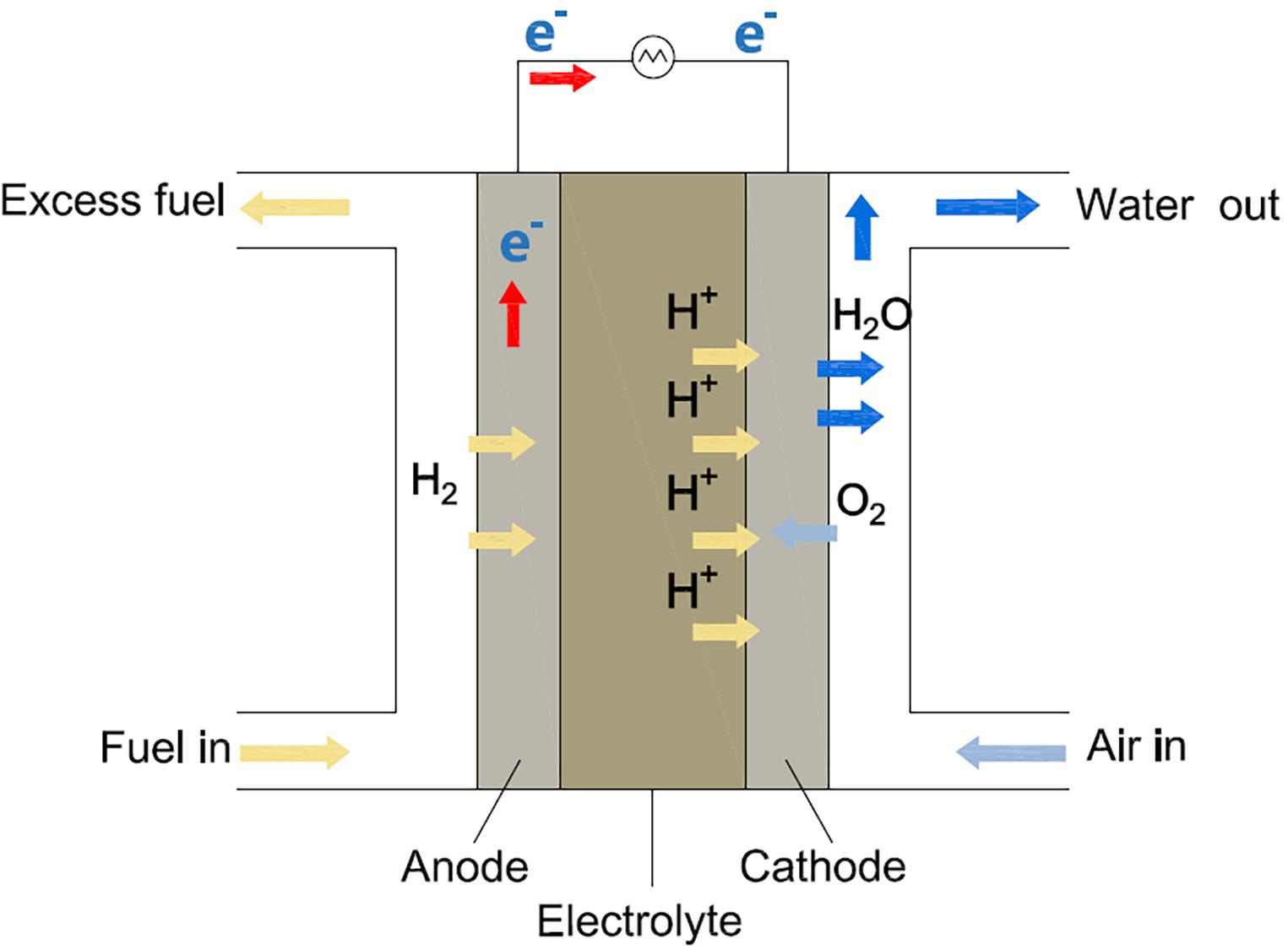
Figure 1. The principle of proton exchange membrane fuel cell (PEMFC).
The development of fuel cell stack mainly includes technology innovations of bipolar plate, membrane electrode assembly (MEA) and integration of cells.
The structure and properties of the bipolar plate play a decisive role in cell performance and reliability. According to the material, bipolar plates are classified as graphite plates, metallic plates and composite plates[5]. The graphite bipolar plate has the advantages of strong corrosion resistance and high durability, accompanied by the disadvantages of a large size and a high cost. The metallic plate is mechanically strong and light, but is susceptible to corrosion and passivation. The composite plate has good corrosion resistance, but its electrical and thermal conductivity are lower than that of graphite plates and metal plates. As to the aspect of durability requirement for commercial vehicles, the graphite bipolar plate has more competitive advantages than metals at present. In addition to the properties of the bipolar plate, the flow field design and gas intake mode affect the distribution of reactants inside the fuel cell. Common flow fields include parallel, serpentine, interdigitated and other derived flow fields shown in Figure 2, and the comparison of different flow fields is summarized in Table 1. For conventional parallel flow filed, fuel cells with U-type flow fields perform better than that of Z-type in most cases for large manifolds [6].
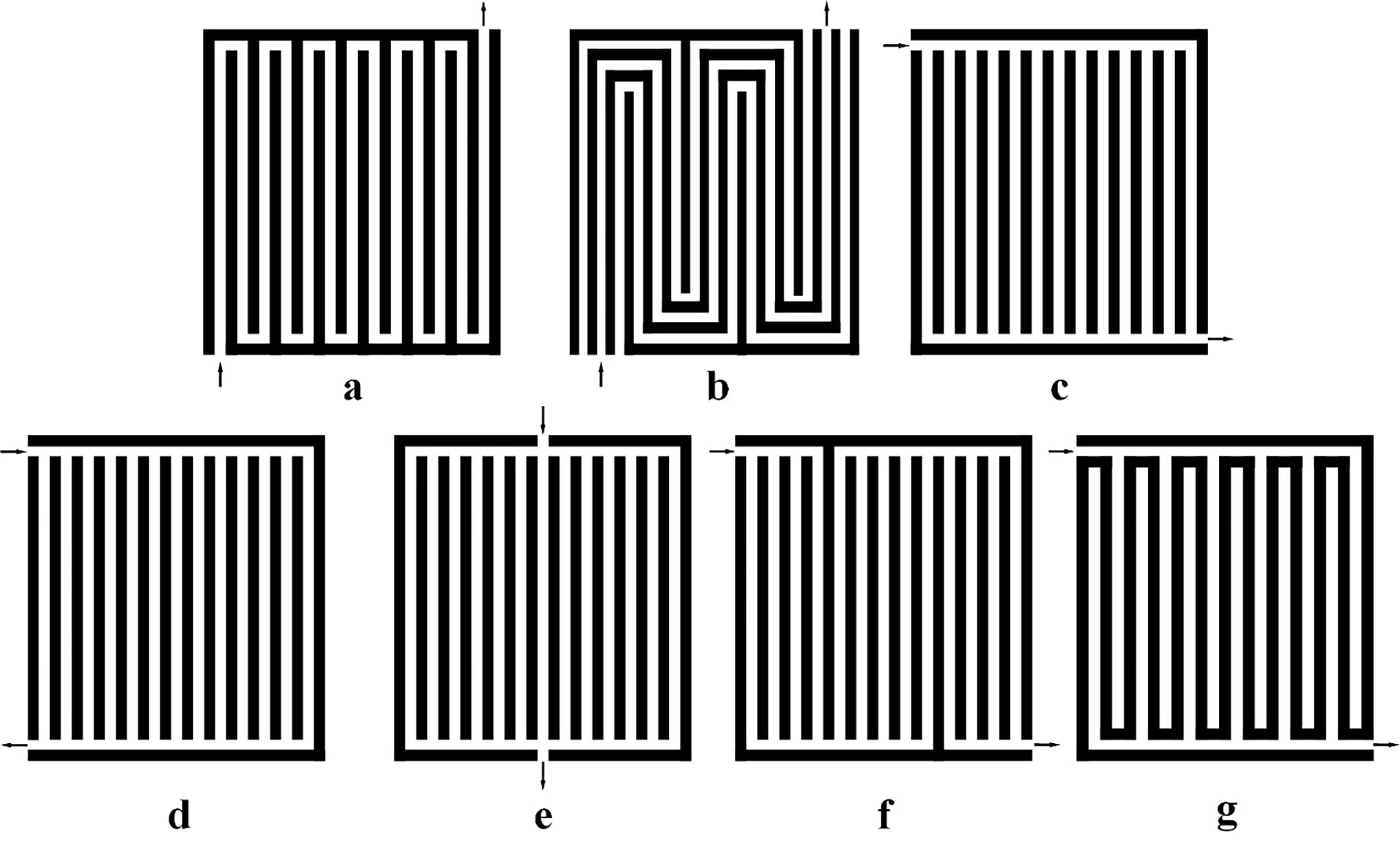
Figure 2. Different flow fields. (a) Serpentine flow field (single); (b) Serpentine flow field (multiple); (c) Parallel flow field; (d) U-type parallel flow field; (e) U-type symmetric flow field; (f) Parallel in series (discontinuous type); (g) Interdigitated flow field.
Table 1 Comparison of different flow fields [8].

Metal bipolar plates are commonly used in FCVs. The anti-corrosion technology for long durability, precision molding technology for fine mesh flow field and welding technology for the reduce of strain accumulation are the key to high-performance metal bipolar plates.
MEA is the core component of the fuel cell, which is composed of gas diffusion layers (GDLs), catalyst layers (CLs) and proton exchange membranes (PEMs). GDLs are composed of carbon fiber substrates and microporous layers, which play the functions of gas diffusion, water transfer, heat transfer, current collection and CLs support. CLs are porous layers composed of catalyst particles and ionomers, which promote the occurrence of electrochemical reactions. And proton exchange membrane has the functions of conducting protons and blocking reactants.
The key materials and preparation technology are the focus of research and development of GDLs [9]. Chen et al. [10] studied the effect of GDL with different PTFE contents on the thermal conductivity and the performance of PEMFC. Silva et al. [11] applied electrospray techniques for the preparation of GDL to form a good distribution of PTPE and realized the improvement of cell performance. For CLs, the electrocatalyst with high activity and low PT load is explored to reduce the cost of catalyst [12]. Ostroverkh et al. [13] examined the MEA with magnetron sputtering electrodes and found significantly less platinum per unit area. Gradient cathode CL shown in Figure 3 was proposed to retain high electrochemical surface area (ECSA) and gain more uniform Pt mass distributions to improve the durability of PEMFC [14]. For membrane, the ultrathin composite perfluorinated sulfonate proton exchange membrane is the focus of future development. Mohanty et al. [15] investigated the effect of membrane thickness and ionomer volume fraction on the cell performance. Due to the reduced ohmic resistance, thinner membranes achieve enhanced PEMFC performance. For ultrathin membranes, the mechanical properties and chemical durability have to be taken into account.

Figure 3. Gradient cathode CL structures.
Packaging and sealing technology are the key to fuel cell integration. The following study focused on the commercialization of PEMFC stack and the components assembly technics for the stack [16,17]. Song et al.[16] summarized the assembly load and assembly load optimization for PEMFC stacks, and pointed out that the automation is the direction of PEMFC stack assembly technique. Porstmann et al [17]. developed requirements specifications for automated PEMFC stack production and designed a large-scale manufacturing machine to achieve a reduction in assembly time.
2.2.Hydrogen Supply System
The hydrogen subsystem is vital to meet the demand for hydrogen during the operation of PEMFC, and to ensure safe, stable, and efficient operation of the system. Hydrogen circulation pumps and ejectors are the key components of hydrogen supply systems, and the schematic of different hydrogen supply subsystems is shown in Figure 4. Han et al. [18] reviewed the hydrogen recirculation components of fuel cell vehicles, including mechanical pumps, ejectors and gas-water separators. To achieve small volume, low noise and low power consumption, a hydrogen circulating pump was presented, but has the operating difficulty (without lubricant) and high requirements for components such as seals and explosion-proof functions. Zhang et al. [19] conducted CFD simulations to evaluate the performance of a scroll-type hydrogen pump for FCVs. Pressure ratio and rotating speed were the main factors to reduce shaft power. He et al. [20] proposed a model predictive control approach to regulating the hydrogen circulation of a 100 kW PEMFC system, where two linearization models were constructed for the low-power case and high-power case to study the hydrogen mass flow dynamic characteristics, and then a switched MPC scheme was designed to achieve the efficient and stable operation of the PEMFC.
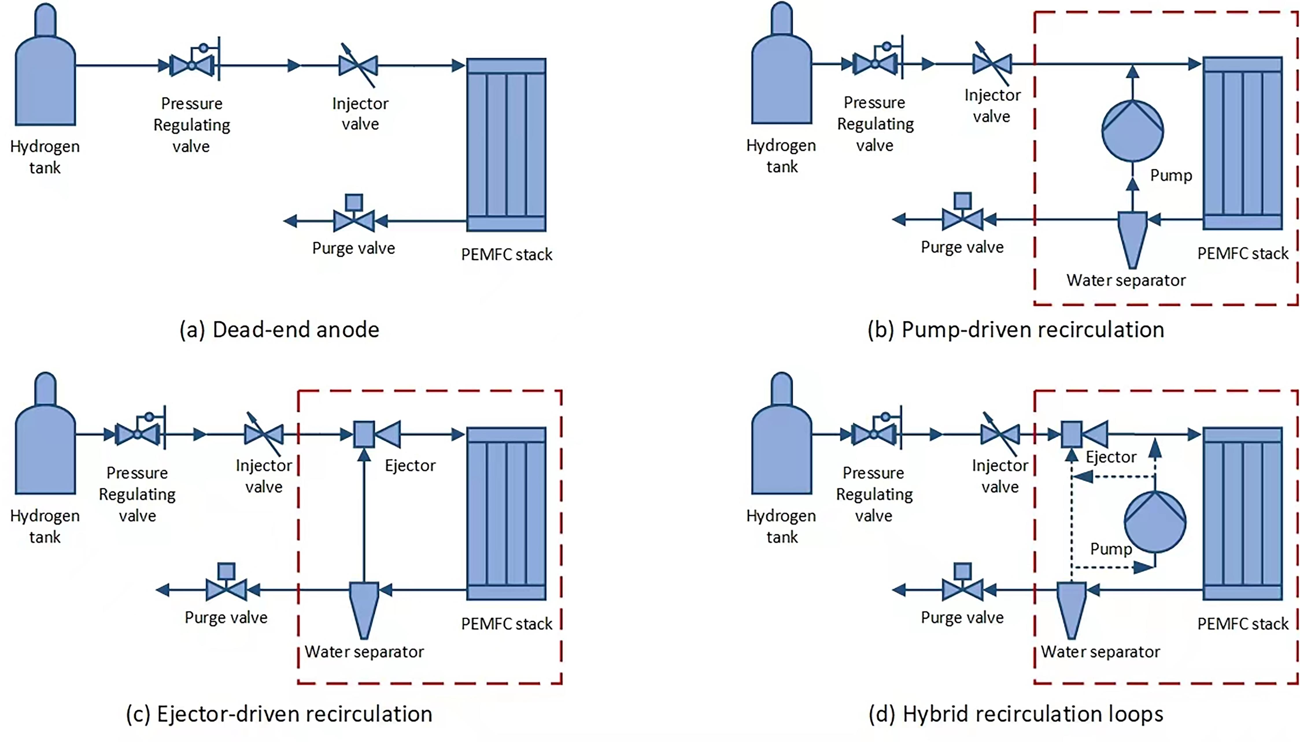
Figure 4. Schematic diagram of different hydrogen supply subsystems.
In contrast, the ejector has the advantages of the simple structure, low maintenance cost, good sealing and wide application. However, the amount of circulating hydrogen by the ejector is greatly affected by the hydrogen flow rate and the operating range of the ejector is narrow, which results in the poor performance of the fuel cell system at low power. Yan et al. [21] conducted numerical simulations to study the effect of geometric parameters and operating conditions on the ejector performance. The results showed the secondary flow tube inlet diameter has significant effect on the ejector recirculation ratio compared with slight effect of the secondary flow tube convergence and inclination angles. And both the secondary flow relative humidity and temperature significantly influenced the ejector performance. Xue et al. [22] designed a multi-nozzle ejector to obtain a wide operating range for hydrogen recirculation of PEMFC, and investigated the performance of the ejector numerically and experimentally. The results showed that the collaboration of nozzles performed superior recirculation capacity due to the restriction of vortices, and the two-nozzle operating mode exhibited the best recirculation capacity.
The current status of variable ejector technologies for the stable operation of a wide power range and the development of the stepless switchable multi-stage ejector technology are solutions for high-power fuel cell systems.
2.3.Air Supply System
The air subsystem is used to supply air to the fuel cell stack for power generation and consists of air filters, air compressors, intercoolers, humidifiers, backpressure valves and other components. Through parameters matching and optimal design, the air supply system achieves the best regulation of the temperature, humidity, flowrate, pressure, and other parameters. Zhou et al. [23] designed an integrated air supply device to meet the air demand of multi-stack fuel cell systems (Figure 5). The results showed that the integrated air supply device could reduce both the maximum electrical power and the electrical power consumption compared with the parallel structure for air supply. Deng et al. [24] adopted a cascade adaptive sliding mode control to regulate the oxygen stoichiometric ratio for PEMFC air supply systems. The proposed control technique could avoid the situation that the oxygen excess ratio reached the critical value of 1, and could extend the stack life.
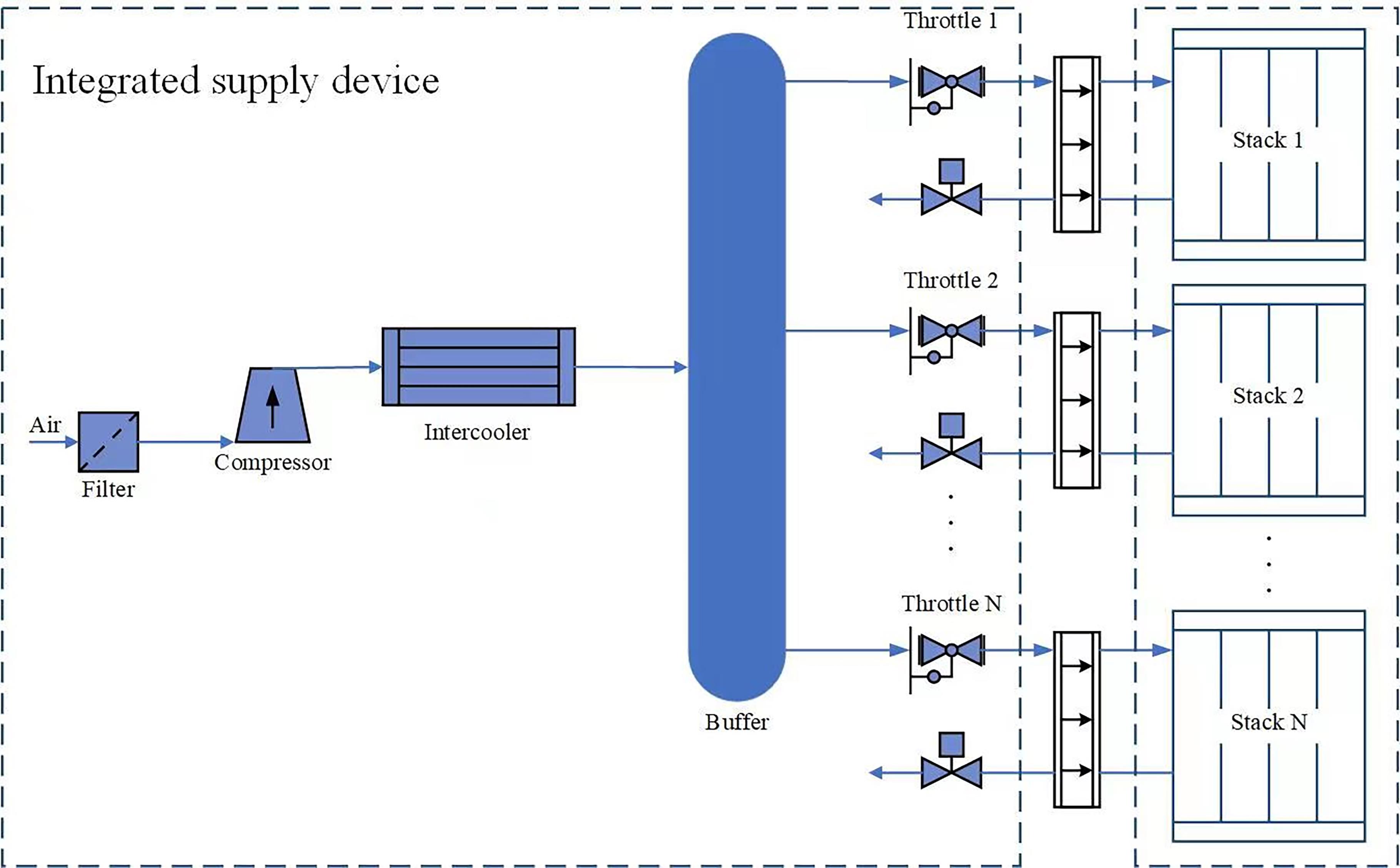
Figure 5. An integrated air supply device.
In addition, the air compressor is the core component of the fuel cell system, which is the largest energy consuming device in the auxiliary BOP (balance of plant) system and has a great impact on the efficiency of fuel cell systems. The amount of humidification water under high operation pressure is significantly reduced, which can greatly reduce the volume of the humidifier or even cancel it. Hou et al. [25] summed up the types and characteristics of fuel cell compressors. Considering the compression ratio, pulsation, performance map and cost, roots, centrifugal and supercharger or turbocharger were suitable for fuel cell compressors.
The most important control objects in gas supply process of fuel cell engine are the stoichiometry of oxygen and air pressure, while the matching and control technologies for pressurization, humidification, and heat dissipation of cathode air remain to be hot research directions in the future.
2.4.Thermal Management System
Due to the limited conversion efficiency of fuel cells, part of the chemical energy is converted into heat, which requires a thermal management system to control the temperature within an appropriate range to keep the fuel cell operating properly. The main components of the thermal management system are radiators, cooling water pumps, PTC heaters and other key components.
The current research and optimization of thermal management systems mainly focuses on heat dissipation structure, coolant and control strategies. In terms of heat dissipation structure, Gong et al. [26] studied the flow and heat transfer characteristics of Roewe 950 and Toyota Mirai (Figure 6). By increasing the area of the intake grille and optimizing the window opening angle of the radiator, the heat transfer coefficient could be improved, where a new windward bending structure was developed to improve the heat transfer rate of the radiator [27]. In terms of coolant, Zakaria et al.[28] found that 40:60 hybrid TiO2:SiO2 nanofluid coolant enhanced cooling performance and reduced discharge intensity relative to the heat transfer rate at higher flow rates. For control strategies, based on the Kalman filter algorithm, Wei [29] used the predicted temperature as the core control parameter to keep the temperature difference between the inside of PEMFC and the inlet and outlet of coolant in a low range. Han et al. [30] designed a feedback controller including model reference adaptive control (MRAC) to control the stack and coolant inlet temperature. The results show that the MRAC algorithm achieves better transient performance in terms of recovery speed and deviation compared with the nominal feedback control algorithm.

Figure 6. Structure of inlet grille and computation model of Roewe 950 and Mirai. Reprinted/adapted with permission from [26].
In general, thermal management systems are moving toward higher heat transfer efficiency radiator structures, lower electrical discharge strength and higher heat transfer rate coolants, faster responses and enhanced robustness control strategies.
2.5.Fuel Cell System Control
Due to the complexity, strong coupling and nonlinear characteristics of PEMFC, higher requirements are placed on the design and development of the control system. The control of the FCV system requires fast and accurate response of the actuators to ensure the correct coordination among the subsystems and meet the normal operation of the vehicle under complex operating conditions. Combining common algorithms such as neural network control, fuzzy control, and adaptive control, the fuel cell controller is developed to achieve faster adjustment, smaller steady-state error, less oscillation, and better anti-interference capability, resulting in higher fuel cell output power, service life, and power supply efficiency. Daud et al. [31] summarized the PEMFC system control, including the reaction, thermal, water management and power management subsystem, and paid special attention to control strategies to avoid fuel starvation. They pointed out that the use of neural network control and fuzzy logic control could be successfully implemented with simple applications, low costs and better results. Han et al. [32] proposed an effective surge control algorithm under various operating conditions in an automotive fuel cell system. The adaptive control showed faster responses, smaller overshoot, and restored faster at the air flow rate compared with the feedback control, which performed effectively for robust air flow management. Reddy et al. [33] presented an adaptive neuro-fuzzy inference system (shown in Figure 7) based maximum power point tracking controller and achieved an increase of average DC link power and a reduce of average response time. Yang et al. [34] proposed a novel robust fault observer for the fault diagnosis based on the linear parameter-varying model, where the augmented robust observer could accurately estimate the system states and faults under different conditions.
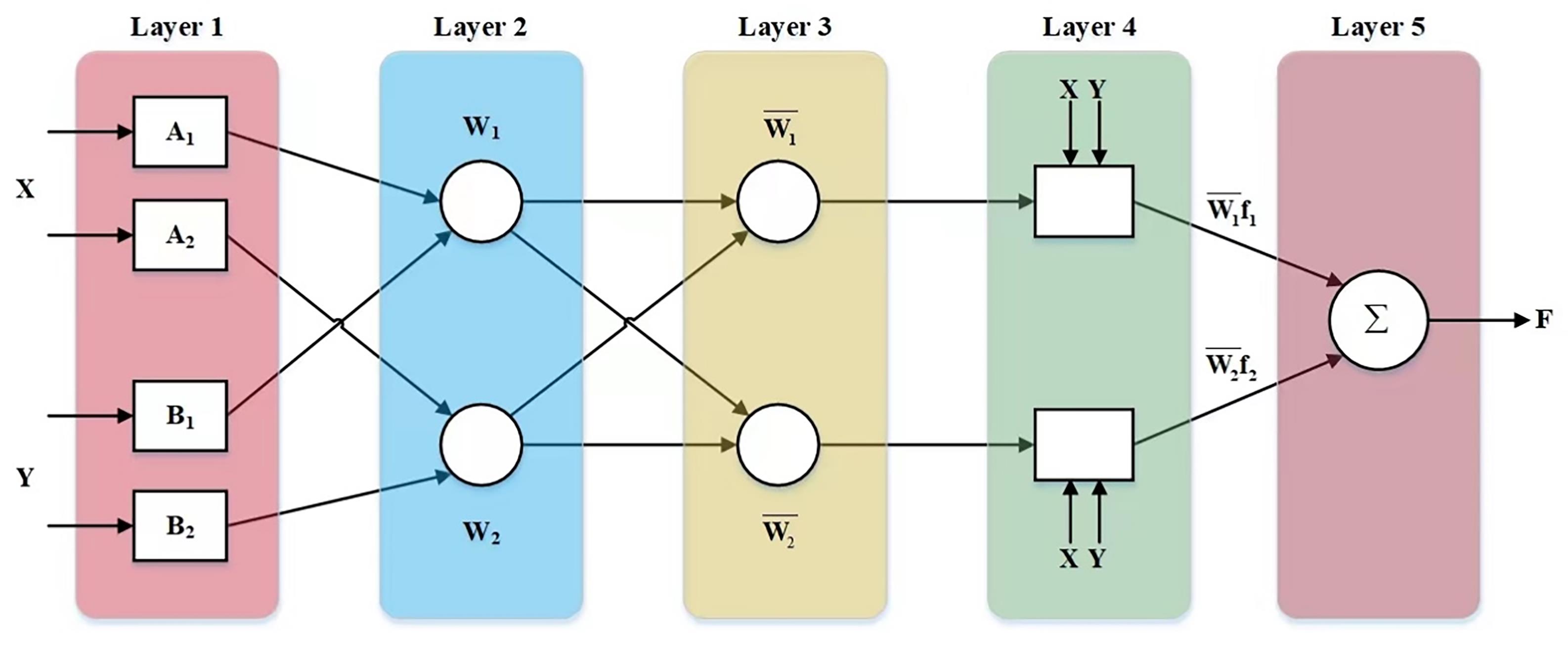
Figure 7. Adaptive neuro-fuzzy inference system architecture.
In addition to the control strategy, DC/DC converter is also a key component of the fuel cell control system, which enables precise control of the fuel cell engine output power to achieve power distribution and optimal control between the vehicle's power systems. Wang et al. [35] compared high voltage gain DC/ DC boost converters employed for FCVs. A proper power conditioning unit should be high efficiency, voltage gain ratio and compactness, low weight, volume and cost. Electrochemical impedance spectroscopy integrated with the DC/DC converter was a promising approach for FCVs due to the limited space.
The key to the efficient and stable operation of fuel cell systems is to construct the cooperative control mechanism and realize the integrated design of fuel supply, energy comprehensive utilization, fault diagnosis and comprehensive evaluation.
2.6.Fuel Cell System Integration
Through the balance of plant (BOP) matching, the fuel cell system integration technology organically integrates the hydrogen supply system, air supply system, thermal management system and control system to achieve the optimal comprehensive indicators of the system structure, performance, life and cost. For commercial vehicles, fuel cell system integration needs to satisfy good durability and long lifetime, environmental adaptability and suitable economy. For passenger vehicles, high volumetric power densities are also required due to space limitation.
Toyota Mirai FCV and Honda Clarity FCV are typical development of fuel cell system technologies. Hasegaw. et al. [36] analyzed the details of the Toyota Fuel Cell system employed in Mirai FCV, from the configuration of TFCS and the external humidifier-less system. By optimizing the stack structure and the anode operating conditions, the fuel cell system without an external humidifier promoted the diffusion of water and the uniformly distribution of the water. Toshihiko and Koichi [37] focused on the reducing cost and improving performance of Mirai FCV. A novel 3-D fine mesh flow field, i.e., the new PtCo alloy catalyst and thinner membrane were adopted in Mirai FCV to reduce the resistance of the mass transfer and electronic to improve the performance of the fuel cell stack. The newly design of the hydrogen tank, streamlining of the FC system and leverage of mass-produced parts could reduce the weight and costs for the developing of a hydrogen society. The key technologies of new Mirai were investigated by Yoshizumi et al [38]. In a partially narrowed channel, the use of mesoporous carbon as a catalyst support, along with the highly oxygen-permeable ionomer and high speed sealing are beneficial for enhancing the power performance and reducing the size of the stack (Figure 8). Tanaka et al. [39] described the fuel cell system for Honda Clarity. By optimizing the structure of the fuel cell stack and controlling water distributions, the Clarity FCV could achieve high performance and long durability.
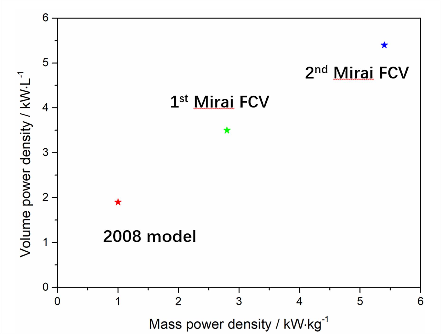
Figure 8. Power density of FC stack.
Compared with passenger vehicles, China has more advantages and potential in the field of commercial FCVs, especially in the field of long-distance heavy-duty transportation. Çabukoglu et al. [40] developed a data-driven approach to evaluate the option of decarbonize heavy-duty truck drove on hydrogen in Swiss. The extensive construction of hydrogen stations and multiple times of refueling hydrogen could bring the conversion rate of heavy-duty fleet to fuel cell vehicles close to 100%. Camacho et al. [41] collected and analyzed the available information of hydrogen fuel cell heavy-duty trucks. Public policies, hydrogen supply chain, environmental impact, drivetrain technology, fuel cell applications were the main topic of the researches (Figure 9). Sun et al. [42] introduced a novel control strategy consisting of feed-forward and internal model decoupling control for air supply of heavy vehicle fuel cell engine. The results showed that the strategy could realize the independent control of air flow and pressure and guarantee the tracking of required airflow and pressure. Cullen et al. [43] discussed the necessary improvement of fuel cells in heavy-duty transportation based on the current passenger FCVs. Except for the hydrogen infrastructure challenges, system strategies such as voltage clipping, material strategies such as optimized catalyst–support interactions, were effective to develop new classes of hydrogen vehicle with high efficiency, power density and scalability.

Figure 9. Main research topics of hydrogen fuel cell heavy-duty trucks.
The technical route of commercial FCV development is to develop a drive chassis that meets the characteristics of full-power commercial FCV arrangement, design a new vehicle appearance to improve the power and economy of the whole vehicle, and optimize the component design and control strategy to realize the rapid response of the power system under the conditions of variable load.
3.Conclusions
This paper analyzed the development of FCV technologies from the fuel cell stack to system integration, including the key materials, key components, thermal management technology, system control technology at home and aboard, and pointed out the direction of future fuel cell commercial vehicle development.
The main obstacles of the application of fuel cell industrialization in China are the lifespan and the gap of performance. For domestic companies, they still have a long way to go towards improving the performance and durability of the fuel cell stack in contrast to famous foreign companies. The integrated system of high-specific power and long-life hydrogen power systems can be further developed by means of (1) the research and development of key materials of high-performance, low-cost and long-life hydrogen power systems, (2) the matching research of key components of fuel cells, and (3) the coupling managements of water, heat, gas and electricity. In addition, necessary measures for the industrialization development of China's commercial FCV include (1) the cooperation with vehicle energy management and thermal management, (2) the development of key technologies for hydrogen commercial FCVs, (3) the establishment of development processes, vehicle calibration and test evaluation specifications, and (4) the achievement of key performance improvement indicators.
Author Contributions: Conceptualization and methodology, W.R.; formal analysis, investigation, data curation, writing—original draft preparation, J.S.; writing—review and editing, C.D.; visualization, supervision, project administration and funding acquisition, X.L. All authors have read and agreed to the published version of the manuscript.
Funding: This research was funded by Key R&D project of Hubei Province, grant number 2021AAA006. The APC was funded by Key R&D project of Hubei Province.
Data Availability Statement: The data used to support the findings of this study are available from the corresponding author upon request.
Acknowledgments: The authors would like to thank Zhengbai Liu for helpful discussions on topics related to this work.
Conflicts of Interest: The authors declare that they have no known competing financial interests or personal relationships that could have appeared to influence the work reported in this paper.
References
- Olabi A.G. ; Bahri A.S. ; Abdelghafar A.A. ; et al . Large-vscale hydrogen production and storage technologies: current status and future directions. International Journal of Hydrogen Energy, 2021, 46(45): 23498-23528. DOI: https://doi.org/10.1016/j.ijhydene.2020.10.110
- Ajanovic A. ; Haas R . Prospects and impediments for hydrogen and fuel cell vehicles in the transport sector. International Journal of Hydrogen Energy, 2021, 46(16): 10049-10058. DOI: https://doi.org/10.1016/j.ijhydene.2020.03.122
- Ajanovic A. ; Haas R . Economic and environmental prospects for battery electric- and fuel cell vehicles: a review. Fuel Cells, 2019, 19(5): 515-529. DOI: https://doi.org/10.1002/fuce.201800171
- Scott K. ; Shukla A .K. Polymer electrolyte membrane fuel cells: principles and advances. Reviews in Environmental Science and Bio/Technology, 2004, 3(3): 273-280. DOI: https://doi.org/10.1007/s11157-004-6884-z
- Kuan Y.D. ; Ciou C.W. ; Shen M.Y. ; et al . Bipolar plate design and fabrication using graphite reinforced composite laminate for proton exchange membrane fuel cells. International Journal of Hydrogen Energy, 2021, 46(31): 16801-16814. DOI: https://doi.org/10.1016/j.ijhydene.2020.08.030
- Amirfazli A. ; Asghari S. ; Sarraf M . An investigation into the effect of manifold geometry on uniformity of temperature distribution in a PEMFC stack. Energy, 2018, 145: 141-151. DOI: https://doi.org/10.1016/j.energy.2017.12.124
- Manso A.P. ; Marzo F.F. ; Barranco J. ; et al . Influence of geometric parameters of the flow fields on the performance of a PEM fuel cell. A review. International Journal of Hydrogen Energy, 2012, 37(20): 15256-15287. DOI: https://doi.org/10.1016/j.ijhydene.2012.07.076
- Lim B.H. ; Majlan E.H. ; Daud W .R.W.; et al. Effects of flow field design on water management and reactant distribution in PEMFC: a review. Ionics, 2016, 22(3): 301-316. DOI: https://doi.org/10.1007/s11581-016-1644-y
- Mortazavi M. ; Santamaria A.D. ; Chauhan V. ; et al . Effect of PEM fuel cell porous media compression on in-plane transport phenomena. Journal of Power Sources Advances, 2020, 1: 100001. DOI: https://doi.org/10.1016/j.powera.2020.100001
- Chen T. ; Liu S.H. ; Zhang J.W. ; et al . Study on the characteristics of GDL with different PTFE content and its effect on the performance of PEMFC. International Journal of Heat and Mass Transfer, 2019, 128: 1168-1174. DOI: https://doi.org/10.1016/j.ijheatmasstransfer.2018.09.097
- Silva L .M.G.; Leocádio G.N.; de Souza R.F.B.; et al. New approach by electrospray technique to prepare a gas diffusion layer for the proton exchange membrane fuel cell anode. Materials Today Advances, 2021, 12: 100161. DOI: https://doi.org/10.1016/j.mtadv.2021.100161
- Guo Y.Q. ; Pan F.W. ; Chen W.M. ; et al . The controllable design of catalyst inks to enhance PEMFC performance: a review. Electrochemical Energy Reviews, 2021, 4(1): 67-100. DOI: https://doi.org/10.1007/s41918-020-00083-2
- Ostroverkh A. ; Dubau M. ; Johánek V. ; et al . Efficient Pt-C MEA for PEMFC with low platinum content prepared by magnetron sputtering. Fuel Cells, 2018, 18(1): 51-56. DOI: https://doi.org/10.1002/fuce.201700137
- Zheng Z.F. ; Yang F. ; Lin C. ; et al . Design of gradient cathode catalyst layer (CCL) structure for mitigating Pt degradation in proton exchange membrane fuel cells (PEMFCs) using mathematical method. Journal of Power Sources, 2020, 451: 227729. DOI: https://doi.org/10.1016/j.jpowsour.2020.227729
- Mohanty S. ; Desai A.N. ; Singh S. ; et al . Effects of the membrane thickness and ionomer volume fraction on the performance of PEMFC with U-shaped serpentine channel. International Journal of Hydrogen Energy, 2021, 46(39): 20650-20663. DOI: https://doi.org/10.1016/j.ijhydene.2021.03.252
- Song K. ; Wang Y.M. ; Ding Y.H. ; et al . Assembly techniques for proton exchange membrane fuel cell stack: a literature review. Renewable and Sustainable Energy Reviews, 2022, 153: 111777. DOI: https://doi.org/10.1016/j.rser.2021.111777
- Porstmann S. ; Wannemacher T. ; Richter T . Overcoming the challenges for a mass manufacturing machine for the assembly of PEMFC stacks. Machines, 2019, 7(4): 66. DOI: https://doi.org/10.3390/machines7040066
- Han J.Q. ; Feng J.M. ; Chen P. ; et al . A review of key components of hydrogen recirculation subsystem for fuel cell vehicles. Energy Conversion and Management: X, 2022, 15: 100265. DOI: https://doi.org/10.1016/j.ecmx.2022.100265
- Zhang Q.Q. ; Feng J.M. ; Zhang Q.Q. ; et al . Performance prediction and evaluation of the scroll-type hydrogen pump for FCVs based on CFD–Taguchi method. International Journal of Hydrogen Energy, 2019, 44(29): 15333-15343. DOI: https://doi.org/10.1016/j.ijhydene.2019.04.019
- He H.W. ; Quan S.W. ; Wang Y .X. Hydrogen circulation system model predictive control for polymer electrolyte membrane fuel cell-based electric vehicle application. International Journal of Hydrogen Energy, 2020, 45(39): 20382-20390. DOI: https://doi.org/10.1016/j.ijhydene.2019.12.147
- Yin Y. ; Fan M.Z. ; Jiao K. ; et al . Numerical investigation of an ejector for anode recirculation in proton exchange membrane fuel cell system. Energy Conversion and Management, 2016, 126: 1106-1117. DOI: https://doi.org/10.1016/j.enconman.2016.09.024
- Xue H.Y. ; Wang L. ; Zhang H.L. ; et al . Design and investigation of multi-nozzle ejector for PEMFC hydrogen recirculation. International Journal of Hydrogen Energy, 2020, 45(28): 14500-14516. DOI: https://doi.org/10.1016/j.ijhydene.2020.03.166
- Zhou S. ; Xie Z.H. ; Chen C.G. ; et al . Design and energy consumption research of an integrated air supply device for multi-stack fuel cell systems. Applied Energy, 2022, 324: 119704. DOI: https://doi.org/10.1016/j.apenergy.2022.119704
- Deng H.W. ; Li Q. ; Cui Y.L. ; et al . Nonlinear controller design based on cascade adaptive sliding mode control for PEM fuel cell air supply systems. International Journal of Hydrogen Energy, 2019, 44(35): 19357-19369. DOI: https://doi.org/10.1016/j.ijhydene.2018.10.180
- Hou J.B. ; Yang M. ; Ke C.C. ; et al . Control logics and strategies for air supply in PEM fuel cell engines. Applied Energy, 2020, 269: 115059. DOI: https://doi.org/10.1016/j.apenergy.2020.115059
- Gong C.Y. ; Shen J. ; Yu Y. ; et al . Heat dissipation characteristic in the intake grille and radiator of a fuel cell vehicle. International Journal of Green Energy, 2020, 17(10): 591-601. DOI: https://doi.org/10.1080/15435075.2020.1779078
- Gong C.Y. ; Du Y.M. ; Yu Y. ; et al . Numerical and experimental investigation of enhanced heat transfer radiator through air deflection used in fuel cell vehicles. International Journal of Heat and Mass Transfer, 2022, 183, Part C: 122205. DOI: https://doi.org/10.1016/j.ijheatmasstransfer.2021.122205
- Zakaria I.A. ; Mohamed W .A.N.W.; Azid N.H.A.; et al. Heat transfer and electrical discharge of hybrid nanofluid coolants in a fuel cell cooling channel application. Applied Thermal Engineering, 2022, 210: 118369. DOI: https://doi.org/10.1016/j.applthermaleng.2022.118369
- Wei Y.Q. ; Zhao Y.L. ; Yun H .T. Research on PEMFC internal temperature predictions and thermal management strategy based on a Kalman algorithm. Journal of Energy Engineering, 2021, 147(3): 04021010. DOI: https://doi.org/10.1061/(ASCE)EY.1943-7897.0000753
- Han J. ; Yu S. ; Yi S . Advanced thermal management of automotive fuel cells using a model reference adaptive control algorithm. International Journal of Hydrogen Energy, 2017, 42(7): 4328-4341. DOI: https://doi.org/10.1016/j.ijhydene.2016.10.134
- Daud W .R.W.; Rosli R.E.; Majlan E.H.; et al. PEM fuel cell system control: a review. Renewable Energy, 2017, 113: 620-638. DOI: https://doi.org/10.1016/j.renene.2017.06.027
- Han J. ; Yu S. ; Yi S . Adaptive control for robust air flow management in an automotive fuel cell system. Applied Energy, 2017, 190: 73-83. DOI: https://doi.org/10.1016/j.apenergy.2016.12.115
- Reddy K.J. ; Sudhakar N . ANFIS-MPPT control algorithm for a PEMFC system used in electric vehicle applications. International Journal of Hydrogen Energy, 2019, 44(29): 15355-15369. DOI: https://doi.org/10.1016/j.ijhydene.2019.04.054
- Yang D. ; Wang Y.J. ; Chen Z .H. Robust fault diagnosis and fault tolerant control for PEMFC system based on an augmented LPV observer. International Journal of Hydrogen Energy, 2020, 45(24): 13508-13522. DOI: https://doi.org/10.1016/j.ijhydene.2020.03.063
- Wang H.Q. ; Gaillard A. ; Hissel D . A review of DC/DC converter-based electrochemical impedance spectroscopy for fuel cell electric vehicles. Renewable Energy, 2019, 141: 124-138. DOI: https://doi.org/10.1016/j.renene.2019.03.130
- Hasegawa T. ; Imanishi H. ; Nada M. ; et al . Development of the fuel cell system in the Mirai FCV: 2016-01-1185. Pittsburgh: SAE International, 2016. DOI: https://doi.org/10.4271/2016-01-1185
- Yoshida T. ; Kojima K . Toyota MIRAI fuel cell vehicle and progress toward a future hydrogen society. The Electrochemical Society Interface, 2015, 24(2): 45-49. DOI: https://doi.org/10.1149/2.F03152if
- Yoshizumi T. ; Kubo H. ; Okumura M . Development of high-performance FC stack for the new MIRAI: 2021-01-0740. Pittsburgh: SAE International, 2021. DOI: https://doi.org/10.4271/2021-01-0740
- Tanaka S. ; Nagumo K. ; Yamamoto M. ; et al . Fuel cell system for Honda CLARITY fuel cell. eTransportation, 2020, 3: 100046. DOI: https://doi.org/10.1016/j.etran.2020.100046
- Çabukoglu E. ; Georges G. ; Küng L. ; et al . Fuel cell electric vehicles: an option to decarbonize heavy-duty transport? Results from a Swiss case-study. Transportation Research Part D: Transport and Environment, 2019, 70: 35-48. DOI: https://doi.org/10.1016/j.trd.2019.03.004
- de las Nieves Camacho, M.; Jurburg D. ; Tanco M . Hydrogen fuel cell heavy-duty trucks: review of main research topics. International Journal of Hydrogen Energy, 2022, 47(68): 29505-29525. DOI: https://doi.org/10.1016/j.ijhydene.2022.06.271
- Sun T. ; Zhang X. ; Chen B. ; et al . Coordination control strategy for the air management of heavy vehicle fuel cell engine. International Journal of Hydrogen Energy, 2020, 45(39): 20360-20368. DOI: https://doi.org/10.1016/j.ijhydene.2019.10.134
- Cullen D.A. ; Neyerlin K.C. ; Ahluwalia R.K. ; et al . New roads and challenges for fuel cells in heavy-duty transportation. Nature Energy, 2021, 6(5): 462-474. DOI: https://doi.org/10.1038/s41560-021-00775-z


