
Downloads
Download


This work is licensed under a Creative Commons Attribution 4.0 International License.
Review
Dimethyl Ether to Power Next-Generation Road Transportation
Simon LeBlanc , Xiao Yu , Linyan Wang , and Ming Zheng *
Department of Mechanical, Automotive and Materials Engineering, University of Windsor, 401 Sunset Avenue, Windsor, N9B 3P4 Ontario, Canada
* Correspondence: mzheng@uwindsor.ca
Received: 20 March 2023
Accepted: 8 June 2023
Published: 19 June 2023
Abstract: The prevailing transportation uses internal combustion engines powered by fossil fuels that bear the reputation of carbon dioxide release among other harmful emissions. As an alternative, dimethyl ether (DME) has shown a high potential to mitigate emission challenges. The properties of DME present a highly reactive and volatile fuel suitable for clean combustion. However, the onboard handling of liquified DME is an ongoing challenge, especially for high-pressure direct injection applications. This paper aims to evaluate the sustainability, fuel handling, and combustion characteristics of DME as a clean and efficient fuel for sustainable on-road transportation. Strategies toward integrating DME fuel for automotive applications are emphasized. An overview of DME production is provided with relevance to current industry practices. Thereafter, the chemical and physical properties of DME are highlighted. The handling challenges of DME are accentuated, and accordingly, recommendations are made for setting up fuel management systems applicable to on-road engines and research laboratories. The DME fueling configurations, e.g., port injection and direct injection, are summarized. Empirical tests studied the engine and emission performance of DME combustion. Ultra-low NOx and smoke emissions, with high combustion efficiency, are achieved.
Keywords:
emission control alternative fuel emission reduction fuel injection combustion process1. Introduction
Industrial progression, technological advances, and population growth have fueled a continuous increase in global energy demand. From 1980 to 2020, global primary energy consumption increased by 100% [1]. Fossil-based energy sources such as coal, natural gas, and crude oil support 92% of energy production [1]. Crude oil consumption in transportation accounted for 20% of global energy consumption [2] and an estimated 18% share of the total CO2 emissions, a leading greenhouse gas (GHG) [3, 4]. Crude oil has controlled the transportation energy market for over a century, largely in part to internal combustion engines (ICEs) powering road, rail, and maritime applications. The high energy density of liquid hydrocarbon fuel allows for minimal weight and volume demand for onboard energy storage [5].
Government regulations have progressively tightened vehicle tailpipe emissions with the intent of minimizing environmental pollution and fuel consumption [6]. In parallel, ICE research and development have proved capable to meet regulations with modernizations, which simultaneously increased energy efficiency and reduced emissions [7]. From 1990 to 2020, the fuel consumption of light-duty vehicles and heavy-duty vehicles has reduced by around 30% and 40%, respectively [8, 9]. The development of ICEs and aftertreatment technology balances the trade-off between tailpipe emissions and fuel consumption [10]. Continued advances in ICE technologies are one of the many actions necessary to successfully transition to sustainable and net-zero transportation [11, 12].
Alternative fuel is considered as one that displaces crude oil consumption or lowers net carbon dioxide (CO2) emissions [13]. Table 1 lists alternative fuels and their respective storage and handling, engine strategy, and fueling system. The majority of alternative fuels aim to lower CO2 emissions such as ethanol, biodiesel, and dimethyl ether (DME) [14]. Hydrogen and ammonia are carbon-free energy sources that have gained attention towards decarbonizing transportation by eliminating tailpipe CO2 emissions [15, 16].
Table 1. Alternative Fuels.

Alcohols, esters, and ethers have been regarded as attractive renewable fuels for ICEs. Ethanol (alcohol) has a low cetane number suitable for spark ignition (SI) engines. Biodiesel (ester) and DME (ether) have a high cetane number suitable for compression ignition (CI) engines. However, the high vapour pressure of DME necessitates a pressurized storage system similar to liquefied petroleum gas (LPG) systems. The physical characteristics of DME impede the adoption of DME as a fuel, especially for direct injection CI engines. On the other hand, the gaseous nature of DME permits low-pressure port injection fueling without concern for mixing ability.
Fuels of similar physical properties can be readily blended. For this reason, blending liquid biofuels with petroleum fuels is a popular solution to lowering CO2 emissions. Federal regulations have targeted such strategies by mandating renewable fuel content. For example, in the United States of America, petroleum diesel is mixed with ~5% biodiesel content (B5) and gasoline with ~10% bioethanol content (E10). Fuels of poor chemical compatibility with component sealing materials are limited in volume to the ICE hardware aptitude, for example, the high permeability of ethanol towards conventional elastomers [17]. New components or fuel additives may be supplemented to reduce surface scuffing of the fuel injection system. Fuels that are physically and chemically unsuited to current fuel systems are often used as a neat fuel and require a fuel system conversion, such as DME.
This paper aims to evaluate the properties, handling, and combustion of DME as a clean and efficient fuel for sustainable transportation, to emphasize the strategies for incorporating DME fuel for combustion research and vehicle applications.
2. Dimethyl Ether (DME) Production
2.1. Syngas
DME is produced from synthetic gas (syngas). Syngas is an energy carrier consisting primarily of CO, H2, CO2, and traces of other gases. In general, syngas is treated and filtered, then adjusted to the appropriate CO:H2 ratio for its subsequent conversion processes to produce DME [18]. Other constituents of the syngas mixture-CO2 and water-are carefully monitored and often incorporated in the synthesis process [19].
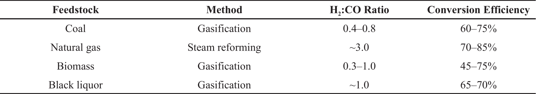
Syngas production is dominated by efficient and resource-abundant natural gas steam reforming (see Table 2). However, DME production via natural gas-based syngas translates to a minimal reduction in net carbon emissions [20].
Table 2. A summary of syngas conversion processes [19].
The use of renewable feedstocks which participate in the carbon cycle is essential to lower the carbon intensities of ICE fuels. In this regard, it is considered that biomass and renewable power (wind and solar) are highly valuable feedstocks. As renewable electricity generation expands in the efforts to decarbonize the electrical grid, syngas from renewable power sources can be integrated upstream without alteration to ICE vehicles [21]. A combination of electrolysis and direct air CO2 capture powered by renewable electricity can produce renewable syngas:

2.2. Conversion Processes
DME is produced in two ways. A two-step approach wherein syngas is converted to methanol and then synthesized to DME, commonly referred to as the indirect method. The catalysis reaction can be summarized as follows:

Secondly, a hybrid catalyst combines both catalytic functions from the hydrogenation of CO ( Equation 2) and dehydration of methanol ( Equation 3) to offer a single-step approach. The direct method of syngas conversion to DME can be represented by the following reaction:

The direct conversion process operates at a temperature of 200–300 ℃ and a pressure of 30-70 bar [22]. The indirect method operates at 220–400 ℃ and a much lower pressure of 1–30 bar [22]. DME production via the direct method is the most efficient [23]. However, the direct method involves increased complexity of additional cooling and safety precautions as the process is exothermic and prone to cause thermal run-away [21]. For this reason, the two-step indirect approach is the most commercially established method.
2.3. Energy Efficiency and Carbon Intensity
The net energy and carbon intensity of a fuel depends on several factors, namely: (1) feedstock choice, (2) conversion & refinement processes, (3) transportation & distribution, and (4) end-use efficiency. Factors (1) to (3) are considered well-to-tank (WTT) while factor (4) is considered the tank-to-wheel (TTW) [24]. Among alternative fuels for ICEs, the TTW intensities are fairly similar, while WTT can differ significantly. The WTT carbon intensities of various syngas-based fuels are primarily influenced by the feedstock to produce syngas and a lower energy intensity equally results in lower carbon intensity.
Natural gas is most efficient as a DME feedstock, in some reports achieving up to 68% fuel energy conversion efficiency [19], albeit far from diesel fuel refinement which can achieve ~90% fuel conversion efficiency [25]. DME fuel conversion efficiency using coal, biomass, and electricity as feedstocks are estimated to be 60%, 53%, and 55%, respectively [19]. In comparison, Fischer-Tropsch (FT) fuel conversion efficiencies of 52% have been reported [26]. FT-synthesis requires additional pre-treatment and hydrocracking which increases energy consumption [22, 27].
The TTW carbon intensity of DME from natural gas steam reforming is estimated to be 87 gCO2/kWhfuel [28]. If biogas were used as a feedstock, the carbon intensity would drop to -259 gCO2/kWhfuel, a net negative carbon impact [28]. In this lifecycle of renewable DME, the carbon intensity can be extremely low. A technical report on TTW analysis released by the European Commission [24] compared alternative fuels for transportation, as summarized in Figure 1. The report describes DME as one of the lowest carbon-intense fuels. Thus, a plausible system may entail DME production from natural gas which cannot be met via renewable power. As renewable power generation expands, its substitution of natural gas for DME production introduces significant reductions in net GHG emission reductions at the pace of fuel production advancements.

Figure 1. Lifecycle greenhouse gas (GHG) and energy of alternative fuel choices. Adapted with permission from [24].
2.4. Production Facilities
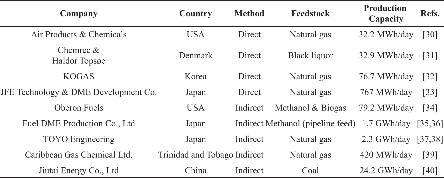
Table 3 lists several currently active DME production facilities. The global production capacity of DME is estimated at 10 million tons per year (210 GWh/day equivalent). Indirect method facilities generally have higher production capacity than direct method plants. Many countries have proposed plans for future DME plant developments. A strong intent for such plans aims to lessen fossil fuel imports by using domestic fossil energy, especially in coal-rich nations. For example, a large-scale coal-to-DME plant with a planned production capacity of 1.4 million tons per year (equivalent to ~27 GWh/day) has recently been approved for construction in Indonesia [29].
Table 3. Active dimethyl ether (DME) production facilities.
The indirect method presents an economic advantage over direct method plants as methanol and DME can be produced with flexibility. New plants can be optimized for DME production via the direct method while existing methanol plants could be extended for DME production for rapid market penetration via the indirect method.
3. DME Handling
The physical and chemical properties of DME are reviewed in this section to explain the handling techniques suitable for DME. A list of selected fuel properties of DME is presented in Table 4. DME is the simplest ether compound of two methyl groups linked by an oxygen atom, with a chemical formula of C 2H 6O. DME is a polar molecule that is considered the root cause of its solvent nature towards elastomers, solubility in water (6% by mass), low boiling point, and high vapour pressure [41]. The chemical conversion processes for DME production fundamentally allow for zero sulphur content.
Table 4. Properties of Dimethyl Ether.

3.1. Fuel System
The management of a diesel high-pressure direct injection system generally consists of supply, return, and injection lines, as shown in Figure 2a. In comparison, the implementation of DME, a gaseous fuel, requires modification as shown in Figure 2b. Primarily, the fuel return lines should be fitted with pressure or temperature regulation to limit fuel pressure. The high vapour pressure of DME demands a closed-loop pressurized system to ensure DME fuel is in liquid form at the supply, injection, and return lines. It is essential to ensure the pumping plenums are free from vapour pockets entirely. Any vapour contents at the pump inlet and injector interior will cause escalated wear and eventual cavity damage. Besides, an incursion of fuel vapour at injection will significantly alter the fuel metering quantity and introduce engine speed and load malfunction.
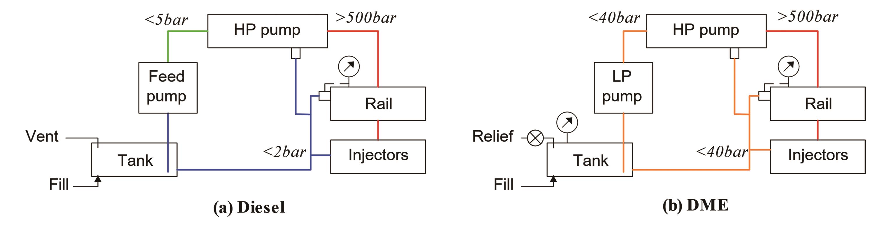
Figure 2. General overview of a high-pressure direct injection fuel system using ( a) diesel and ( b) dimethyl ether (DME).
3.1.1. Low-Pressure System
The DME return line pressure is expected to be 5.1 bar minimum (20 ℃) and further increase with temperature, as shown in Figure 3 [42]. For practical heavy-duty engines, fuel temperature in the supply line can reach as high as 80–120 ℃, requiring more than 40 bar background pressure in the fuel return loop if DME is used. Additional pressure levels or cooling heat exchangers can assist to maintain liquid DME [43].
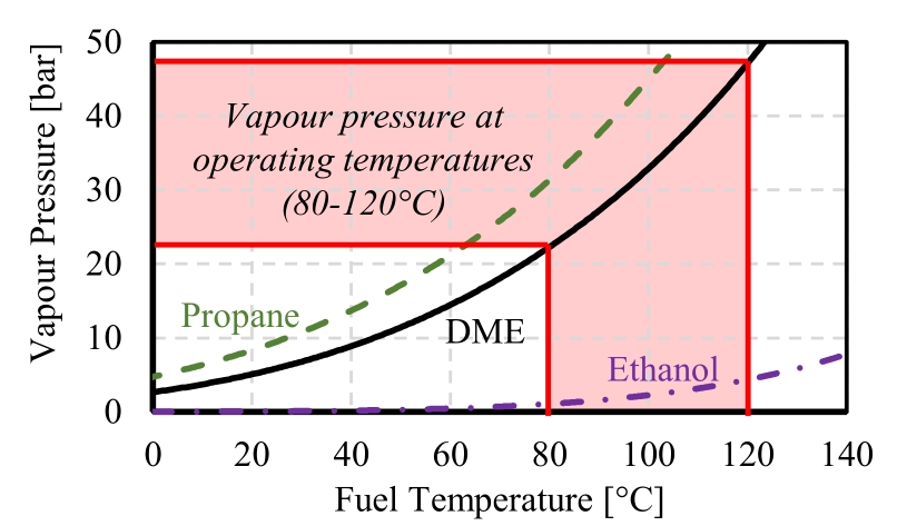
Figure 3. The vapour pressure at a range of fuel temperatures for DME, propane, and ethanol. Data is estimated from the Clausius-Clapeyron equation.
The fuel tank design requirements for DME are considered like that of propane systems, with lower storage pressure. The onboard storage of DME is expected to be ~250% of the volume of diesel fuel tanks to match the same driving range [23].
3.1.2. High-Pressure System
The fuel properties of DME do not permit a direct substitution with diesel fuel using traditional diesel injection hardware; that is, the higher vapour pressure, lower viscosity and lubricity, and corrosive nature towards elastomers. Some components can be used without modification, such as fuel lines, common-rail reservoirs, and sensors.
The difference in energy density subsequently alters the injection energy supply rates. A larger DME fuel injection quantity is required to match the original power rating of the engine when using diesel fuel. A longer injection duration or higher fuel injection pressure can balance the energy supply rate. It is often suggested that DME injectors have an increased volumetric flow rate through larger nozzle hole diameters compared to diesel injectors to match the energy flow rates. From volumetric energy density calculations, the injector nozzle hole should be ~40% larger in diameter than those of diesel engines under matching injection pressures.
Raising the injection pressure of DME to that of current diesel systems, e.g., over 2000 bar, may prove redundant owing to the enhanced atomization characteristics. Moreover, the compressibility of DME is higher than diesel thus incurring additional work during the compression process. Theoretically, DME is expected to consume 1.6 to 3.2 times more compression work to raise its pressure compared with diesel fuel [44]. Therefore, a lower injection pressure should be considered to minimize pumping work.
3.2. Practices
Developing a high-pressure direct injection system suitable for DME fuel is an ongoing challenge, largely owing to its low boiling point. On-board DME fueling systems for industrial applications are more involved than diesel systems. On the other hand, laboratory environments such as single-cylinder research engines can avoid some of the complexities to perform high-pressure DME direct injection research.
3.2.1. Industry
Sustaining liquified DME is of the highest priority. During operation, return lines require prompt monitoring and control as the vapour pressure of DME rises with temperature (see Figure 3). Without an additional thermal management heat exchanger unit or a circulation pump, the return line pressures may require up to 40 bar. For example, Fleisch et al. [45] applied a hydraulic-electronic-unit-injector for DME direct injection up to 220 bar. DME was supplied with a feed pump at 30 bar and the return loop was fitted with pressure regulators adjusted to 9 bar. McCandless and Li [46] developed an axial piston pump fuel injection system for DME capable of 250 bar pressure that consisted of supply pumps, pressure regulators, and a fuel cooler on the return loop. The system was designed and tested with return line pressures up to 40 bar.
The very poor viscosity of DME–an order of magnitude lower than diesel–degrades the reliability and longevity of the fueling system. The addition of a highly viscous fluid to DME is commonly applied to alleviate the deficiencies. To reach the lower limit of current ASTM viscosity specifications, the blending of diesel to DME directly showed a necessary minimum concentration of 10 wt.% [47]. In such cases, the ideal additive to DME should tend to form a protective film on the metal surfaces to increase lubricity such as a polar-headed and long-chain molecule fluid [48]. Some commonly used DME additives that have shown mildly successful include Lubrizol 539 (~0.1%) [49- 51], Infineum R655 (0.05%) [52, 53], Castor oil (1~2%) [54, 55]. Sorenson and Mikkelsen [56] tested the durability of DME (99.9% purity) without additives in a standard diesel pump. The pump performed marginally well until failure after 590 hours of operation, roughly half the expected lifetime of the pump. Also, signs of fuel leaking may reside at the fuel storage tank, injection pump, or injector needle seal [57]. Independent durability studies showed that wear may still be prevalent using the aforementioned additives [58].
The strong solvent nature of DME, especially towards elastomers, requires retrofitting common nitrile rubber seals in the injection pumps to more resistant materials. It is generally recommended that DME-specific seals be made with anticorrosive material, usually a synthetic rubber polymer such as ethylene propylene terpolymer rubber (EPDM). Some research suggests coating with polytetrafluoroethylene (PTFE or Teflon™) as an option [46, 59]. Brusstar et al. [60] designed a high-pressure DME injector specifically fitted with PTFE seals where possible and Buna-N in non-critical locations. The internal surfaces of the injector were treated with a tungsten carbide/carbon coating to protect against seizing, corrosion, and surface wear.
3.2.2. Laboratory
The handling of DME in a laboratory environment can be approached differently than in industry, because of the less intensive use and tolerance on system durability. While fuel pressure and temperature management of DME remains, an alternate injection pump can be applied. Yoshio et al. [51] used an off-board jerk-type in-line injection pump for up to 400 bar fuel pressure. DME was supplied with a feed pump directed to the injection pump inlet. The return loop was fitted with a cooler and returned to the DME tank. A DME fueling system for laboratory investigations was developed by AVL [61], as shown in Figure 4. The supply and return loops include pressure regulators and fuel coolers.
Figure 4. DME handling for engine laboratory studies. Adapted with permission from [61].
Rotary injection pumps with chemically-resistant sealing materials are limited to specialty prototype work with industry or custom fabrication [62]. A single-plunger chemical pump is well suited to pressurize fluids and is often available with seals made of chemically-resistant material. For example, a complete system using a Maximator LSF100-2 is a double-air drive, single-acting pump, as shown in Figure 5. The output fuel pressure is directly proportional to the driving gas pressure. This pump is sealed with Viton O-rings and PTFE material. The injection pressure is stable when the frequency of fuel injection events is low, such as fuel spray research in constant-volume combustion vessels.

Figure 5. Pneumatically-driven plunger-type DME injection pump suitable for research applications.
For applications with frequencies greater than 1 Hz, e.g., engine research, the recycling events of the pump causes instabilities in fuel injection pressure. The plunger resetting event can occur as frequently as every few seconds, during which a large drop in fuel injection pressure is observed [63]. This is especially challenging under high engine load conditions, where the plunger reset frequency increases. The fuel injection fluctuation brings a challenge for engine tests with exhaust gas recirculation (EGR) conditions, where the fluctuation in fuel injection amount directly affects the actual intake oxygen concentration.
A large high-pressure fuel reservoir can be installed between the injection pump and the common rail to minimize the fluctuations. Moreover, the injector fuel return can be directed to the atmosphere. Figure 6 shows a representative fuel system setup. A suitable reservoir volume was estimated to be 300 mL, approximately 10 times the volume of a standard common rail for diesel engines.
Figure 6. A fueling system for handling high-pressure DME for research applications.
This DME fuel system was tested and showed the capability to minimize the fluctuation of the fuel injection pressure during the reset of the plunger. For example, the fuel pressure setpoint of 470 bar experienced a maximum fluctuation of 0.17 bar IMEP and 6 bar injection pressure with the reservoir, improved from a fluctuation of 0.47 bar IMEP and 40 bar injection pressure without the reservoir.
4. DME Combustion
The high chemical reactivity, volatility, and strong aversion to smoke formation can improve combustion efficiency under ultra-low NOx and smoke conditions. Generally, light-duty applications utilize port-injection fueling strategies, whereas heavy-duty is dominated by high-pressure direct injection fueling.
4.1. Direct Injection Strategy
4.1.1. Ignition
In relevance to a non-volatile fuel, such as diesel, the high volatility of DME fuel is considered to enhance fuel-air mixing processes. For direct injection applications specifically, rapid atomization paired with a highly reactive fuel ensures a short ignition delay time.
The cetane number is a fuel property that describes the autoignition tendency, wherein a higher cetane number presents a fuel with a shorter ignition delay period and higher reactivity. Many sources state the cetane number of DME to be 55–60 [64, 65]. Teng et al. [66] applied empirical relationships to engine operation under similar CFR testing protocols and define a cetane number of approximately 68. Though the consensus is absent on the method to certify the cetane number of DME, it is convincingly higher than diesel fuel (Grade No. 2-D), as shown in Figure 7. The marginally higher reactivity under a range of injection advance timings shows the suitability of DME as a substitute for diesel. The ignition disparity of DME and diesel was increasingly apparent as the injection advanced.
Figure 7. The ignition delay of diesel and DME at 600 bar and 550 bar fuel injection pressure, respectively.
4.1.2. NOx and Smoke
The applicable range of common in-cylinder strategies that minimize NOx production, such as heavy EGR, is limited to the inherent NOx-smoke trade-off of diesel combustion, a leading challenge in diesel engine development [67]. While after-treatment technology is effective in meeting tail-pipe emission regulations, complicated aftertreatment systems increase the costs of the vehicle significantly [68].
The high fuel-borne oxygen content of DME, among other factors such as molecular structure and volatility, significantly suppresses smoke generation [69]. As a result, DME combustion emits smoke emissions lower than current and future emission standards, as shown in Figure 8. Hence, the NOx-smoke trade-off is redundant to DME combustion, and NOx control becomes directly managed by the EGR rate.
Figure 8. The NOx-smoke trade-off of diesel compared with DME. All emissions are engine-out. Single-shot fuel scheduling with exhaust gas recirculation (EGR) sweep. The fuel supply fixed was fixed at a 5.6 bar IMEP at 0% EGR (nominal). 2015*: Optional US California HD certification for California low NOx standard. 2027**: Proposed ultra-low NOx program in California.
4.1.3. Efficiency
The ultra-low smoke emissions of DME shift the combustion performance metrics under low-temperature combustion from a NOx-smoke trade-off to a combustion efficiency-NOx trade-off [70]. The combustion efficiency characteristically worsens as engine-out NOx emission reduces due to the lower combustion temperature, as shown in Figure 9. However, DME can sustain high combustion efficiency at lower NOx levels, nearing the upcoming EURO VII hot emission standards. Such trends are observed in other empirical studies compared to diesel [51, 71, 72].
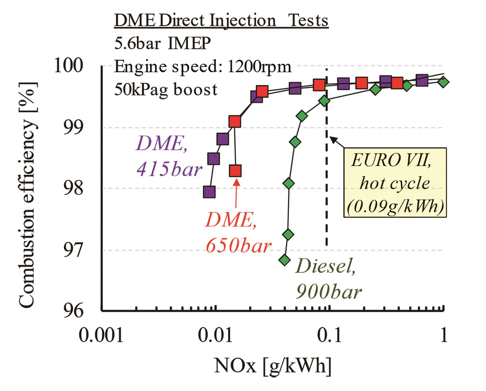
Figure 9. The combustion efficiency-NOx trade-off of DME.
The enhanced volatility, reactivity, and fuel-borne oxygen of DME attest to the enhanced performance under a higher EGR rate. Figure 10 shows the variation of diesel and DME combustion under low engine-out NOx emissions. Table 5 summarizes the operating point and resultant performance and emissions of the cylinder trace shown. Accurate control over the combustion phasing, commonly defined as the crank angle of 50% heat release (CA50), is interrelated to the engine performance and emissions, specifically NOx [73]. As such, the importance of minimizing the cycle-to-cycle variations and precise CA50 control is augmented by operating under low-temperature combustion (LTC). Under such conditions, it can be observed that DME has fewer cyclic variations owing to higher reactivity, enhanced volatility, and a lower dependency on oxygen entrainment.
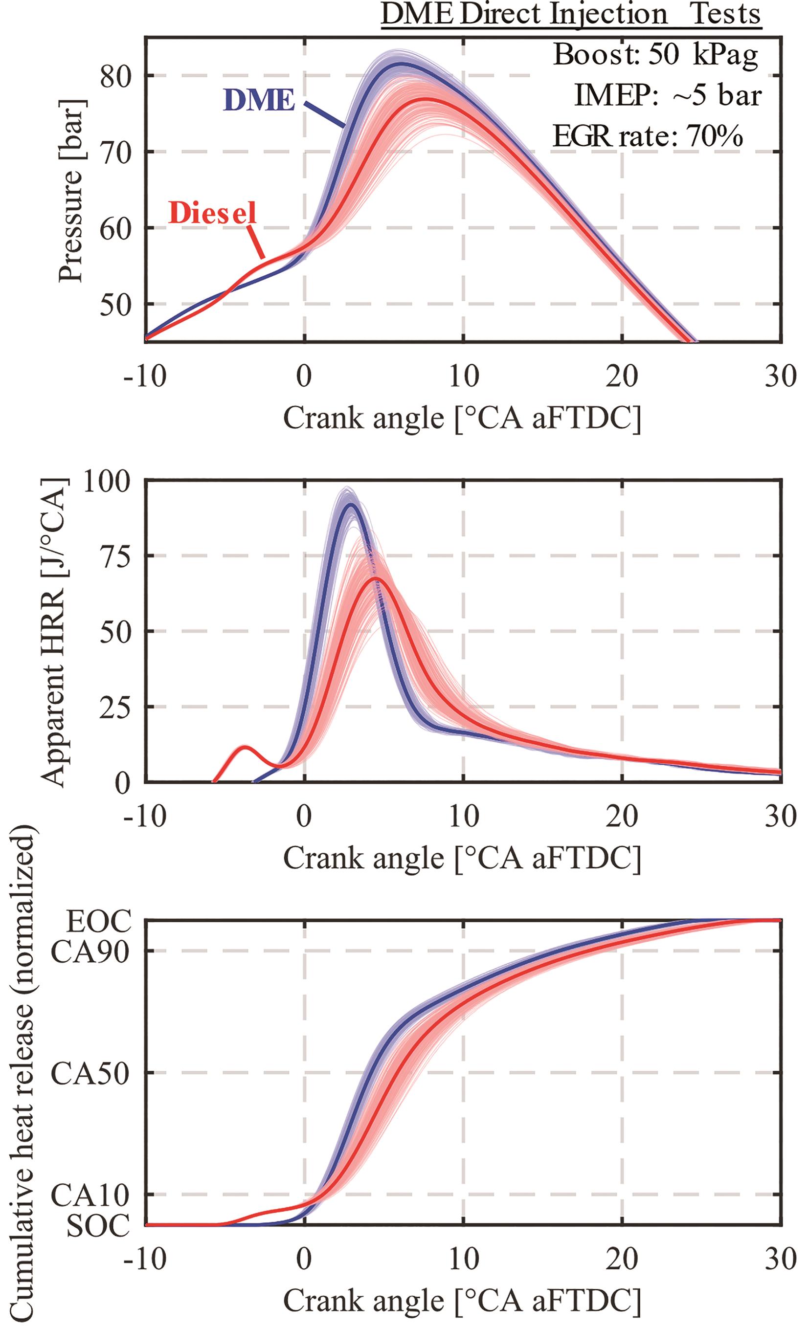
Figure 10. The superimposed history of 200 continuous operating cycles and the average in-cylinder pressure, apparent heat release rate and cumulative heat release of diesel (900 bar fuel pressure) and DME (650 bar fuel pressure) operating at very low NOx conditions. Refer Table 5 for operation and emission details.
Table 5. Engine performance and emission characteristics of diesel and DME combustion at 70% exhaust gas recirculation (EGR) rate.

A report from Oak Ridge National Laboratory in support of Volvo North America published a set of dynamometer tests with a DME-fueled heavy-duty (13 L) prototype vehicle [74]. The results proved similar thermal efficiency between diesel-fueled and DME-fueled engines implicating matching energy consumption. The authors noted that the tests were conducted using the standard diesel fuel injection and control strategies. It is reasonable to expect DME combustion to be further optimized with calibration and hardware development.
4.2. Port Injection Strategy
The low-pressure fueling of port injection systems has less complexity than its high-pressure direct injection counterpart.
4.2.1. Homogeneous Charged Compression Ignition
Homogeneous charged compression ignition (HCCI) systems rely upon chemical kinetics to initiate the combustion process. The ignition timing can be influenced by intake air temperature, compression ratio (CR), and intake dilution using excess air (lean burn) or EGR [75].
Asad [76] showed the combustion characteristics of a CR decrease from 17.8 to 13.1 under maximum operable engine loads. Two heat release stages were apparent with DME combustion, namely the low-temperature heat release (LTHR) and high-temperature heat release (HTHR) stages, as shown in Figure 11. A decrease in CR ensued a delay in LTHR timing by 3 ℃A and HTHR by 2 ℃A. The maximum allowable engine load was increased from 0.87 bar to 2.1 bar IMEP all the while reaching lower maximum in-cylinder pressure and improved combustion phasing. Largely, the engine load was limited by the maximum pressure rise rate and combustion noise.

Figure 11. The effect of compression ratio on the cylinder pressure and heat release rate. Adapted with permission from [76].
EGR dilution serves as an effective strategy for delaying the autoignition timing and limiting pressure rise rates [77]. Unlike altering the CR, EGR can be readily changed during operation and therefore can be used as a combustion phasing control strategy. Pedersen et al. [78] studied the influence of EGR on DME HCCI on a 4-cylinder ISUZU truck engine by overriding the injection command to inject at the beginning of the intake stroke. The original piston bowl was modified to reduce the CR from 19 to 14.5. The increase of EGR from 0% to 70% proved an engine load increase of 25%, from 2 bar to 2.5 bar BMEP. Over the same EGR range, the combustion timing was delayed by 10 ℃A, albeit still before firing top dead center (FTDC). Previous work at the authors' laboratory [79] investigated the influence of intake CO2 dosing (simulated EGR) on stoichiometric DME HCCI combustion at 9.2 CR. A maximum engine load increase of 3 bar to 4 bar IMEP was observed from 0% to 9.3% intake CO2 concentration. The appropriate EGR rate balances a combustion phasing window that is knocking-limited in the early phasing, while stability-limited in the late phasing of combustion [80].
4.2.2. Spark-Assisted Compression Ignition
Excessive EGR rates can be employed if additional means of control are added such as a spark discharge. With significant EGR dilution and a combustion phasing beyond optimal timing, a spark event can act as an ignition timing control to advance combustion. Simultaneous control of these parameters achieved an engine load of 7.8 bar IMEP with 13% intake CO2, 2 bar abs. intake boost pressure, and spark discharge at 35 ℃A before top dead center (TDC), as shown in Figure 12 [79].

Figure 12. The cylinder pressure and apparent heat release rate of port injection DME with intake CO2 dilution and spark assistance.
5. Conclusions
This work made an effort to describe the suitability of DME as a sustainable energy source to support the energy transition of combustion engines in transportation. The presented work communicated the following:
1. The indirect method (2-step process) presents an economic advantage with dual-capable methanol and DME production plants, and the flexibility of proportioning either fuel to follow market demands. The use of fossil fuels dominates large-scale plants while renewable feedstocks are increasing in popularity for small-scale plants and pilot projects.
2. The fuel properties of DME do not permit for a direct substitution with diesel fuel using traditional diesel injection hardware; that is, the higher vapour pressure, lower viscosity and lubricity, and corrosive nature towards elastomers. The fueling system of DME requires a pressurized fuel return of up to 40 bar to ensure liquid DME for high-pressure pumping.
3. The high-pressure injection of DME in a laboratory environment can be approached differently than in the industry, because of the less intensive use and tolerance on system durability. A pneumatic drive single-plunger pump made of chemically-resistant material can operate high-pressure DME without the use of additives. The injector return line is diverted toward the atmosphere to ease the fuel system management.
4. The high reactivity of DME proves the suitability of DME as a substitute for diesel. The challenging NOx-smoke trade-off of diesel combustion is nonexistent to DME combustion. The ultra-low smoke emissions of DME shift the combustion performance metrics under low-temperature combustion towards a combustion efficiency-NOx trade-off DME can maintain high combustion efficiency under lower NOx levels, nearing the upcoming EURO VII emission standards.
5. Port injection fueling is subject to fewer DME handling complexities. The combustion timing of DME HCCI can be influenced by the compression ratio, intake air temperature, and dilution, however, limitations persist. The engine load was limited by the maximum pressure rise rate and combustion noise. A combination of the heavy intake charge dilution and spark assistance at a CR of 9.2 was able to reach an engine load of 7.8 bar IMEP.
Author Contributions: Conceptualization, methodology, investigation, S. L., X. Y.; software, validation, resources, writing—original draft preparation, visualization, S.L.; data curation, formal analysis, writing—review and editing, X.Y., L W., M. Z.; supervision, project administration, funding acquisition, M. Z. All authors have read and agreed to the published version of the manuscript.
Funding: This research was partially supported by NSERC/IRC, NSERC/CRD, NSERC/RTI, NSERC/DG, CFI/ORF, Mitacs, and the University of Windsor.
Data Availability Statement: Not applicable.
Acknowledgments: The authors thank the technologist at the University of Windsor, Ford Motor Company of Canada, and other OEM partners for their collaborative effort and technical support.
Conflicts of Interest: The authors declare no conflict of interest.
References
- Statistical Review of World Energy. BP, 2021. Available Online: https://www.bp.com/en/global/corporate/energy-economics/statistical-review-of-world-energy/downloads.html. (Accessed on 3 November 2022).
- Key World Energy Statistics 2021. IEA, Paris, Statistics Report, 2021. Available Online: https://www.iea.org/reports/key-world-energy-statistics-2021. (Accessed on 24 November 2022).
- Transport . IEA, 2022. Available Online: https://www.iea.org/topics/transport. (Accessed on 5 March 2023).
- The role of CCUS in low-carbon power systems. IEA, Paris, 2020. Available Online: https://www.iea.org/reports/the-role-of-ccus-in-low-carbon-power-systems. (Accessed on 24 November 2022)
- Yu X. ; Sandhu N.S. ; Yang Z. ; et al . Suitability of energy sources for automotive application – A review. Applied Energy 2020, 271, 115169. doi: 10.1016/j.apenergy.2020.115169 . DOI: https://doi.org/10.1016/j.apenergy.2020.115169
- Johnson, T. Vehicular Emissions in Review. SAE International Journal of Engines 2016, 9( 2), 1258– 1275. doi: 10.4271/2016-01-0919. DOI: https://doi.org/10.4271/2016-01-0919
- Johnson T. ; Joshi A . Review of Vehicle Engine Efficiency and Emissions. SAE International Journal of Engines 2018, 11( 6), 1307– 1330. DOI: https://doi.org/10.4271/2018-01-0329
- Monthly Energy Review . Department of Energy, Energy Information Administration: Washington, D.C., USA, December 2022. Available online: https://www.eia.gov/totalenergy/data/monthly/previous.php (Accessed on 4 January 2023).
- Bureau of Transportation Statistics: National Transportation Statistics. U.S. Vehicle-Kilometers, 2019. Available Online: https://www.bts.gov/content/us-vehicle-kilometers-0. (Accessed on 4 January 2023).
- Johnson, T.V. Review of Diesel Emissions and Control. SAE International Journal of Fuels and Lubricants 2010, 3( 1), 16– 29, 10.4271/2010-01-0301. doi: DOI: https://doi.org/10.4271/2010-01-0301
- Reitz R.D. ; Ogawa H. ; Payri R. ; et al . IJER editorial: The future of the internal combustion engine. International Journal of Engine Research 2020, 21( 1), 3– 10. doi: 10.1177/1468087419877990 . DOI: https://doi.org/10.1177/1468087419877990
- Kohse-Höinghaus, K. A new era for combustion research. Pure and Applied Chemistry 2019, 91( 2), 271– 288. doi: 10.1515/pac-2018-0608. DOI: https://doi.org/10.1515/pac-2018-0608
- Key Transportation Terminology . U.S. Department of Energy, 2023. Available Online: https://epact.energy.gov/key-terms. (Accessed on 5 March 2023).
- Bae C. ; Kim J . Alternative Fuels for Internal Combustion Engines. Proceedings of the Combustion Institute 2017, 36( 3), 3389– 3413. doi: 10.1016/j.proci.2016.09.009 . DOI: https://doi.org/10.1016/j.proci.2016.09.009
- White C.M. ; Steeper R.R. ; Lutz A . E. The hydrogen-fueled internal combustion engine: a technical review. International Journal of Hydrogen Energy 2006, 31( 10), 1292– 1305. doi: 10.1016/j.ijhydene.2005.12.001 . DOI: https://doi.org/10.1016/j.ijhydene.2005.12.001
- Zamfirescu C. ; Dincer I . Using Ammonia as a Sustainable Fuel. Journal of Power Sources 2008, 185( 1), 459– 465. doi: 10.1016/j.jpowsour.2008.02.097 . DOI: https://doi.org/10.1016/j.jpowsour.2008.02.097
- Durbin T.D. ; Karavalakis G. ; Norbeck J.M. ; et al . Material compatibility evaluation for elastomers, plastics, and metals exposed to ethanol and butanol blends. Fuel 2016, 163, 248– 259. doi: 10.1016/j.fuel.2015.09.060 . DOI: https://doi.org/10.1016/j.fuel.2015.09.060
- Hansen J.B. ; Voss B. ; Joensen F. ; et al . Large Scale Manufacture of Dimethyl Ether - a New Alternative Diesel Fuel from Natural Gas. SAE Transactions 1995, 104, 70– 79. DOI: https://doi.org/10.4271/950063
- Handbook Supplement DME . Tokyo: Japan DME Forum, 2011. Available Online: https://catalog.libraries.psu.edu/catalog/13594717. (Accessed on 24 November 2022)
- Lee U. ; Han J. ; Wang M. ; et al . Well-to-Wheels Emissions of Greenhouse Gases and Air Pollutants of Dimethyl Ether from Natural Gas and Renewable Feedstocks in Comparison with Petroleum Gasoline and Diesel in the United States and Europe. SAE International Journal of Fuels and Lubricants 2016, 9( 3): 546– 557. doi: 10.4271/2016-01-2209 . DOI: https://doi.org/10.4271/2016-01-2209
- Azizi Z. ; Rezaeimanesh M. ; Tohidian T. ; et al . Dimethyl ether: A review of technologies and production challenges. Chemical Engineering and Processing: Process Intensification 2014, 82, 150– 172. doi: 10.1016/j.cep.2014.06.007 . DOI: https://doi.org/10.1016/j.cep.2014.06.007
- Dieterich V. ; Buttler A. ; Hanel A. ; et al . Power-to-liquid via synthesis of methanol, DME or Fischer–Tropsch-fuels: a review. Energy & Environmental Science 2020, 13( 10), 3207– 3252. doi: 10.1039/d0ee01187h . DOI: https://doi.org/10.1039/D0EE01187H
- Verbeek R. ; Van der Weide J . Global Assessment of Dimethyl-Ether: Comparison with Other Fuels. SAE Technical Paper 1997, No. 971607. DOI: https://doi.org/10.4271/971607
- Edwards R. ; Mahieu V. ; Griesemann J . -C.;et al. Well-to-Wheels Analysis of Future Automotive Fuels and Powertrains in the European Context SAE Transactions 2004, 113, 1072– 1084. DOI: https://doi.org/10.4271/2004-01-1924
- Elgowainy A. ; Han J. ; Cai H. ; et al . Energy Efficiency and Greenhouse Gas Emission Intensity of Petroleum Products at U.S. Refineries. Environmental Science & Technology 2014, 48( 13), 7612– 7624. doi: 10.1021/es5010347 . DOI: https://doi.org/10.1021/es5010347
- Van Vliet O.P.R. ; Faaij A.P.C. ; Turkenburg W . C. Fischer–Tropsch diesel production in a well-to-wheel perspective: A carbon, energy flow and cost analysis. Energy Conversion and Management 2009, 50( 4), 855– 876. doi: 10.1016/j.enconman.2009.01.008 . DOI: https://doi.org/10.1016/j.enconman.2009.01.008
- Tremel A. ; Wasserscheid P. ; Baldauf M. ; et al . Techno-economic analysis for the synthesis of liquid and gaseous fuels based on hydrogen production via electrolysis. International Journal of Hydrogen Energy 2015, 40( 35), 11457– 11464. doi: 10.1016/j.ijhydene.2015.01.097 . DOI: https://doi.org/10.1016/j.ijhydene.2015.01.097
- McKone T. ; Rice D. ; Ginn T. ; et al . California Dimethyl Ether Multimedia Evaluation - Tier 1. The University of California, 2015.
- Indonesia starts construction of $ 2. 3 bln coal gasification plant. Reuters, 24 January 2022. Available Online: https://www.reuters.com/business/energy/indonesia-starts-construction-23-bln-coal-gasification-plant-2022-01-24/. (Accessed on 24 November 2022).
- Liquid Phase Dimethyl Ether Demonstration in the LaPorte Alternative Fuels Development Unit . Air Products and Chemicals, Inc. Pennsylvania, Topical Report, 2001. Available Online: https://www.fischer-tropsch.org/DOE/DOE_ reports/90543/90543_demo/defc2292pc90543_demo_toc.htm (Accessed on 24 November 2022).
- Landälv I. ; Gebart R. ; Marke B. ; et al . Two years experience of the BioDME project-a complete wood to wheel concept. Environmental Progress & Sustainable Energy 2014, 33( 3): 744– 750. doi: 10.1002/ep.11993 . DOI: https://doi.org/10.1002/ep.11993
- Chung J. ; Cho W. ; Baek Y. ; et al . Optimization of KOGAS DME process from demonstration long-term test. Transactions of the Korean Hydrogen and New Energy Society 2012, 23( 5), 559– 571, doi: 10.7316/khnes.2012.23.5.559 . DOI: https://doi.org/10.7316/KHNES.2012.23.5.559
- Ohno Y. ; Masahiro Y. ; Tsutomu S. ; et al . New Direct Synthesis Technology for DME (Dimethyl Ether) and Its Application Technology. JFE Technical Report 2006, 8( 7), 34– 40.
- Oberon Fuels rDME . Oberon Fuels. Available Online: https://www.oberonfuels.com/oberons-rdme. (Accessed on 23 November 2022).
- Ishiwada, A. DME Promotion Project in Japan. As A Future Alternative Clean Energy 2011, Nov.
- Production of DME . Japan DME Association. Available Online: http://japan-dme.or.jp/english/dme/production.html. (Accessed on 24 November 2022).
- Mii T. ; Uchida, M. Fuel DME Plant in East Asia . In Proceedings of 15th Saudi-Japan Joint Symposium, Dhahran, Saudi Arabia . 27 November, 2005.
- (Dimethyl Ether) DME . Toyo Engineering Corporation. Available Online: https://www.toyo-eng.com/jp/en/solution/dme/. (Accessed on 24 November 2022).
- Mitsubishi Heavy Industries, Ltd . Global Website | Commercial Operations Commence at Methanol / Dimethyl Ether Plant in Trinidad and Tobago. Mitsubishi Heavy Industries, Ltd. Available Online: https://www.mhi.com/news/210119.html. (Accessed on 24 November 2022).
- Jiutai Energy (Zhangjiagang) Co., Limited . Available Online: https://www.echemi.com/shop-us20180832100041673/index.html. (Accessed on 24 November 2022).
- Arcoumanis C. ; Bae C. ; Crookes R. ; et al . The potential of di-methyl ether (DME) as an alternative fuel for compression-ignition engines: A review. Fuel 2008, 87( 7), 1014– 1030. doi: 10.1016/j.fuel.2007.06.007 . DOI: https://doi.org/10.1016/j.fuel.2007.06.007
- Ether Dimethyl . Linde, Material Safety Data Sheets (MSDS), 2021. Available Online: https://www.lindecanada.ca/-/media/corporate/praxair-canada/documents-en/safety-data-sheet-linde-canada/e-4589-dimethyl-ether-safety-data-sheet-sds.pdf (Accessed on 5 March 2023)
- Huang Z. ; Qiao X. ; Zhang W. ; et al . Dimethyl ether as alternative fuel for CI engine and vehicle. Frontiers of Energy and Power Engineering in China 2009, 3( 1), 99– 108, doi: 10.1007/s11708-009-0013-1 . DOI: https://doi.org/10.1007/s11708-009-0013-1
- Sorenson S.C. ; Glensvig M. ; Abata D . L. Dimethyl Ether in Diesel Fuel Injection Systems. SAE Transactions 1998, 438– 449. DOI: https://doi.org/10.4271/981159
- Fleisch T. ; McCarthy C. ; Basu A. ; et al . A New Clean Diesel Technology: Demonstration of ULEV Emissions on a Navistar Diesel Engine Fueled with Dimethyl Ether. SAE Transactions 1995, 42– 53. DOI: https://doi.org/10.4271/950061
- McCandless J.C. ; Li S . Development of a Novel Fuel Injection System (NFIS) for Dimethyl Ether-and Other Clean Alternative Fuels. SAE Technical Paper 1997, No. 970220. DOI: https://doi.org/10.4271/970220
- Bhide S. ; Morris D. ; Leroux J. ; et al . Characterization of the Viscosity of Blends of Dimethyl Ether with Various Fuels and Additives. Energy & Fuels 2003, 17( 5), 1126– 1132. doi: 10.1021/ef030055x . DOI: https://doi.org/10.1021/ef030055x
- Teng H. ; McCandless J.C. ; Schneyer J . B. Viscosity and Lubricity of (Liquid) Dimethyl Ether - An Alternative Fuel for Compression-Ignition Engines. SAE Technical Paper 2002, No. 2002-01-08 62. doi: 10.4271/2002-01-0862 . DOI: https://doi.org/10.4271/2002-01-0862
- Hansen K.F. ; Nielsen L. ; Hansen J.B. ; et al . Demonstration of a DME (Dimethyl Ether) Fuelled City Bus. SAE Technical Paper 2000, No. 2000-01-20 05. doi: 10.4271/2000-01-2005 . DOI: https://doi.org/10.4271/2000-01-2005
- Yoon S.H. ; Han S.C. ; Lee C . S. Effects of High EGR Rate on Dimethyl Ether (DME) Combustion and Pollutant Emission Characteristics in a Direct Injection Diesel Engine. Energies 2013, 6( 10), 5157– 5167. doi: 10.3390/en6105157 . DOI: https://doi.org/10.3390/en6105157
- Sato Y. ; Nozaki S. ; Noda T . The Performance of a Diesel Engine for Light Duty Truck Using a Jerk Type In-Line DME Injection System. SAE Transactions 2004, 1210– 1222. doi: 10.4271/2004-01-1862 . DOI: https://doi.org/10.4271/2004-01-1862
- Jang J. ; Lee Y. ; Cho C. ; et al . Improvement of DME HCCI engine combustion by direct injection and EGR. Fuel 2013, 113, 617– 624. doi: 10.1016/j.fuel.2013.06.001 . DOI: https://doi.org/10.1016/j.fuel.2013.06.001
- Yeom K. ; Bae C . Knock Characteristics in Liquefied Petroleum Gas (LPG)-Dimethyl Ether (DME) and Gasoline-DME Homogeneous Charge Compression Ignition Engines. Energy & Fuels 2009, 23( 4), 1956– 1964. doi: 10.1021/ef800846u . DOI: https://doi.org/10.1021/ef800846u
- Longbao Z. ; Hewu W. ; Deming J. ; Zuohua H . Study of Performance and Combustion Characteristics of a DME-Fueled Light-Duty Direct-Injection Diesel Engine. SAE Technical Paper 1999, No. 1999-01-36 69. doi: 10.4271/1999-01-3669 . DOI: https://doi.org/10.4271/1999-01-3669
- Junjun Z. ; Xinqi Q. ; Zhen W. ; et al . Experimental Investigation of Low-Temperature Combustion (LTC) in an Engine Fueled with Dimethyl Ether (DME). Energy & Fuels 2009, 23( 1), 170– 174. doi: 10.1021/ef800674s . DOI: https://doi.org/10.1021/ef800674s
- Sorenson S.C. ; Mikkelsen S . -E. Performance and Emissions of a 0.273 Liter Direct Injection Diesel Engine Fuelled with Neat Dimethyl Ether. SAE Transactions 1995, 80– 90. doi: 10.4271/950064 . DOI: https://doi.org/10.4271/950064
- Mccandless J.C. ; Teng H. ; Schneyer J . B. Development of a Variable-Displacement, Rail-Pressure Supply Pump for Dimethyl Ether. SAE Transactions 2000, 818– 826. doi: 10.4271/2000-01-0687 . DOI: https://doi.org/10.4271/2000-01-0687
- Sivebaek I.M. ; Sorenson S . C. Dimethyl Ether (DME) - Assessment of Lubricity Using the Medium Frequency Pressurised Reciprocating Rig Version 2 (MFPRR2). SAE Paper 2000, No. 2000- 01. doi: 10.4271/2000-01-2970 . DOI: https://doi.org/10.4271/2000-01-2970
- Fabiś P. ; Flekiewicz B . Influence of LPG and DME Composition on Spark Ignition Engine Performance. Energies 2021, 14( 17), 5583. doi: 10.3390/en14175583 . DOI: https://doi.org/10.3390/en14175583
- Brusstar M.J. ; Hamady F.J. ; Schaefer R . M. Low Engine-Out NOx Emissions with DME Using High Pressure Injection. SAE Technical Paper 2007, No. 2007-01-40 93. doi: 10.4271/2007-01-4093 . DOI: https://doi.org/10.4271/2007-01-4093
- Gill D.W. ; Ofner H. ; Stoewe C. ; et al . An Investigation into the Effect of Fuel Injection System Improvements on the Injection and Combustion of DiMethyl Ether in a Diesel Cycle Engine. SAE Technical Paper 2014, No. 2014-01-26 58. doi: 10.4271/2014-01-2658 . DOI: https://doi.org/10.4271/2014-01-2658
- Zhen, H. DME as Alternative Fuel for Cl Engine and Vehicle: Progresses in China. 2009. Available Online: https://www.osti.gov/etdeweb/biblio/21341086 (Accessed on 5 March 2023).
- LeBlanc S. ; Jin L. ; Sandhu N.S. ; et al . Combustion Characterization of DME-Fueled Dual Fuel Combustion with Premixed Ethanol. SAE Technical Paper 2022, No. 2022-01-04 61. doi: 10.4271/2022-01-0461 . DOI: https://doi.org/10.4271/2022-01-0461
- Park S.H. ; Lee C . S. Applicability of dimethyl ether (DME) in a compression ignition engine as an alternative fuel. Energy Conversion and Management 2014, 86, 848– 863. doi: 10.1016/j.enconman.2014.06.051 . DOI: https://doi.org/10.1016/j.enconman.2014.06.051
- Patten J. ; McWha T . Dimethyl Ether Fuel Literature Review. National Research Council Canada. Automotive and Surface Transportation. 2015, ST-GV-TR-0032. Available Online: https://nrc-publications.canada.ca/eng/view/object/?id=b22a2fd1-f2fc-40d9-a6f4-cf109f3ea344 (Accessed on 5 March 2023).
- Teng H. ; McCandless J.C. ; Schneyer J . B. Compression Ignition Delay (Physical + Chemical) of Dimethyl Ether – An Alternative Fuel for Compression-Ignition Engines. SAE Transactions 2003, 112, 377– 389. DOI: https://doi.org/10.4271/2003-01-0759
- Zheng M. ; Reader G.T. ; Hawley J . G. Diesel Engine Exhaust Gas Recirculation––A Review on Advanced and Novel Concepts. Energy Conversion and Management 2004, 45( 6): 883– 900. doi: 10.1016/S0196-8904(03)00194-8 . DOI: https://doi.org/10.1016/S0196-8904(03)00194-8
- Posada F. ; Isenstadt A. ; Badshah H . Estimated Cost of Diesel Emissions-Control Technology to Meet Future California Low NOx Standards in 2024 and 2027. The international council on clean transportation (ICCT), May 2020. Available Online: https://trid.trb.org/view/1713385 (Accessed on 5 March 2023).
- Tree D.R. ; Svensson K . I. Soot processes in compression ignition engines. Progress in Energy and Combustion Science 2007, 33( 3), 272– 309. doi: 10.1016/j.pecs.2006.03.002 . DOI: https://doi.org/10.1016/j.pecs.2006.03.002
- Asad U. ; Divekar P. ; Zheng M. ; et al . Low Temperature Combustion Strategies for Compression Ignition Engines: Operability Limits and Challenges. SAE Technical Paper 2013, No. 2013-01-02 83. doi: 10.4271/2013-01-0283 . DOI: https://doi.org/10.4271/2013-01-0283
- Park S.H. ; Lee C . S. Combustion performance and emission reduction characteristics of automotive DME engine system. Progress in Energy and Combustion Science 2013, 39( 1), 147– 168. doi: 10.1016/j.pecs.2012.10.002 . DOI: https://doi.org/10.1016/j.pecs.2012.10.002
- Youn I.M. ; Park S.H. ; Roh H.G. ; et al . Investigation on the fuel spray and emission reduction characteristics for dimethyl ether (DME) fueled multi-cylinder diesel engine with common-rail injection system. Fuel Processing Technology 2011, 92( 7), 1280– 1287. doi: 10.1016/j.fuproc.2011.01.018 . DOI: https://doi.org/10.1016/j.fuproc.2011.01.018
- Asad U. ; Zheng M . Diesel pressure departure ratio algorithm for combustion feedback and control. International Journal of Engine Research 2014, 15( 1), 101– 111. doi: 10.1177/1468087412461268 . DOI: https://doi.org/10.1177/1468087412461268
- Szybist J.P. ; McLaughlin S. ; Iyer S . Emissions and Performance Benchmarking of a Prototype Dimethyl Ether-Fueled Heavy-Duty Truck. Oak Ridge National Laboratory, U.S. Department of Energy, ORNL/TM-2014/59,Feb. 2014. Available Online: https://www.osti.gov/biblio/1150879 (Accessed on 5 March 2023)
- Sato S. ; Iida N . Analysis of DME Homogeneous Charge Compression Ignition Combustion. SAE Technical Paper 2003, No. 2003-01-18 25, doi: 10.4271/2003-01-1825 . DOI: https://doi.org/10.4271/2003-01-1825
- Asad, U. Advanced diagnostics, control and testing of diesel low temperature combustion. Ph. Thesis D. , University of Windsor, Windsor, Ontario, Canada , 2009.
- Putrasari Y. ; Jamsran N. ; Lim O . An investigation on the DME HCCI autoignition under EGR and boosted operation. Fuel 2017, 200, 447– 457. doi: 10.1016/j.fuel.2017.03.074 . DOI: https://doi.org/10.1016/j.fuel.2017.03.074
- Pedersen T.D. ; Schramm J. ; Yanai T. ; et al . Controlling the Heat Release in HCCI Combustion of DME with Methanol and EGR. SAE Technical Paper 2010, No. 2010-01-14 89. doi: 10.4271/2010-01-1489 . DOI: https://doi.org/10.4271/2010-01-1489
- Yu X. ; LeBlanc S. ; Sandhu N. ; et al . Combustion control of DME HCCI using charge dilution and spark assistance. Proceedings of the Institution of Mechanical Engineers, Part D: Journal of Automobile Engineering 2022, 09544070221103361. doi: 10.1177/09544070221103361 . DOI: https://doi.org/10.1177/09544070221103361
- Jung D. ; Iida N . Closed-loop control of HCCI combustion for DME using external EGR and rebreathed EGR to reduce pressure-rise rate with combustion-phasing retard. Applied Energy 2015, 138, 315– 330. doi: 10.1016/j.apenergy.2014.10.085 . DOI: https://doi.org/10.1016/j.apenergy.2014.10.085


